Detection apparatus and detection method for machine tool abnormality

An anomaly detection and tool technology, applied in the direction of measuring devices, manufacturing tools, computer control, etc., can solve the problems of reduced productivity, increased machine tool maintenance costs, reduced processing precision, etc., to achieve maximum reliability and accuracy, small The incidence of defective products and the effect of reducing non-processing time

Active Publication Date: 2020-09-11
DN SOLUTIONS CO LTD
View PDF6 Cites 2 Cited by
  • Summary
  • Abstract
  • Description
  • Claims
  • Application Information

AI Technical Summary

Problems solved by technology

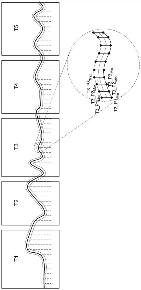
[0013] However, if figure 1 As shown, the existing tool abnormality detection device and detection method of machine tools have the following problems: that is, the maximum load of the spindle is detected and stored in the past to judge whether excessive load is applied to the workpiece, and only when the current load is greater than the maximum load during processing When the load is on, judge whether there is an abnormality in the tool, stop the processing work, but cannot judge the abnormality of the tool with a load below the maximum load
[0014] That is, the conventional tool abnormality detection device and detection method for machine tools have the following problems: that is, when the tool is completely damaged and there is no load, or because the damage of the tool is small and the amount of load fluctuation is small, it is impossible to detect the situation above the maximum load. In this case, even if a tool abnormality occurs, the machining precision is not stopped, and the workpiece is wasted.
[0015] Moreover, the existing tool abnormality detection devices and detection methods for machine tools have the problem that when a tool abnormality occurs, the reliability and precision of the machine tool are reduced due to the inability to accurately judge the situation.
[0016] In addition, in the existing tool abnormality detection device and detection method of the machine tool, there is the following problem: Since the variables of the processing work, the type of workpiece to be processed, and the type of processing tool are not considered at all, the abnormality of the tool is not detected according to the load trend (LOADTREND) of the tool. , Therefore, the staff needs to continuously monitor with the naked eye, so it is inconvenient to the staff, the productivity is reduced, and the maintenance cost of the machine tool is increased.

Method used


Image

  • Detection apparatus and detection method for machine tool abnormality
  • Detection apparatus and detection method for machine tool abnormality
  • Detection apparatus and detection method for machine tool abnormality

Examples


Embodiment Construction

[0042] Hereinafter, a detailed description will be given with reference to diagrams of a tool abnormality detection device and a detection method for a machine tool according to an embodiment of the present invention. The embodiments described below are provided as examples to fully convey the idea of ​​the present invention to those skilled in the art. Therefore, the present invention is not limited to the embodiments described below, but can be embodied in other forms. In addition, in the drawings, the size, thickness, etc. of the device may be shown enlarged for convenience. Throughout the specification, the same symbols denote the same constituent elements.

[0043] The advantages, characteristics, and means for achieving these of the present invention will be clarified by the accompanying drawings and the embodiments described later. However, the present invention is not limited to the following examples, and can be embodied in other various forms. This embodiment is u...


PUM


Abstract

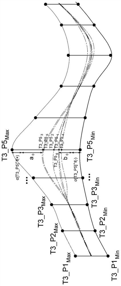
The present invention relates to a detection apparatus and a detection method for machine tool abnormality and, more specifically, to a correction apparatus and a correction method for a backlash of amachine tool which are capable of repeatedly measuring a load of a material transferring part or a material processing part, and automatically detecting an abnormality of a tool on the basis of a normal range of load data that is proportional to a standard deviation of the load data measured on the basis of either the mode value, the mean value, or the median value among repeatedly measured loaddata.

Description

technical field [0001] The present invention relates to a tool abnormality detection device and detection method of a machine tool. More specifically, it relates to a method of repeatedly measuring the load of the workpiece transmission part or the workpiece processing part, based on the repeated measurement of the load data and taking the mode as the standard The standard deviation of the measured load data is compared with the normal range of the proportional load data, and the tool abnormality detection device and detection method of the machine tool can automatically detect whether the tool is abnormal. Background technique [0002] Generally, a machine tool refers to a machine used for the purpose of processing metal / non-metal workpieces into the required shape and size by using appropriate tools through various cutting or non-cutting methods. [0003] Various machine tools such as turning centers, vertical / horizontal machining centers, portal machining centers, switch ...

Claims


Application Information

Patent Timeline
Patent Type & Authority Applications(China)
IPC IPC(8): B23Q17/09G05B19/4065
CPCG05B19/4065G05B2219/50203G05B2219/50276G05B2219/37245G05B2219/50205B23Q17/0961B23Q17/0957B23Q17/0966B23Q17/09G01L5/0028G05B2219/49001
Inventor 沈在杜
Owner DN SOLUTIONS CO LTD
Why Eureka
Try Eureka