
Unmanned bridge crane control system

A technology of control system and general control system, applied in the direction of load hanging components, transportation and packaging, safety devices, etc., can solve the problem of lack of accurate operation site and slag bag data, dynamic monitoring and material information tracking, slag bag Information about lifting equipment status and water-cooling equipment parameters cannot be transmitted in a timely and accurate manner, so as to reduce man-made failures and industrial accidents, facilitate command scheduling and exhibition visits, and meet the needs of intelligent production.

Inactive Publication Date: 2020-09-11
YIMEN COPPER CO LTD
View PDF6 Cites 2 Cited by
  • Summary
  • Abstract
  • Description
  • Claims
  • Application Information

AI Technical Summary

Problems solved by technology

Useful information such as slag bag information, cooling status, hoisting equipment status, and water cooling equipment parameters cannot be transmitted to all aspects of the system in a timely and accurate manner
According to the actual application situation, the existing casting area requires frequent crane operations, high temperature of the buns, harsh operating environment, and easy confusion when casting copper ingots
In addition, full-time operators are required for the operation of the crane. The operators have long operating hours, high labor intensity, boring operation machinery, low production efficiency, and high operating costs. Operators need to frequently get on and off the crane equipment, posing safety hazards; When carrying out operations, it is necessary to cooperate with the ground commander, and there is a lot of human interference
Moreover, there is no accurate operation site and steamed bun and slag bag data, so dynamic monitoring and material information tracking cannot be performed; human interaction between various devices is difficult in management. Once a device failure cannot be found in time, the service life of the device will be short

Method used


Image

  • Unmanned bridge crane control system
  • Unmanned bridge crane control system
  • Unmanned bridge crane control system

Examples


Embodiment Construction

[0022] The following will clearly and completely describe the technical solutions in the embodiments of the present invention with reference to the drawings in the embodiments of the present invention. Apparently, the described embodiments are only some of the embodiments of the present invention, but not all of them. The following description of at least one exemplary embodiment is merely illustrative in nature and not intended as any limitation of the invention, its application or uses. Based on the embodiments of the present invention, other embodiments obtained by persons of ordinary skill in the art without carrying out creative work all belong to the protection scope of the present invention.

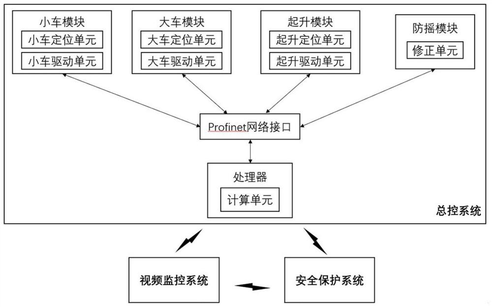
[0023] figure 1 Shown is the system structure block diagram of the present invention. An unmanned crane control system provided by the present invention includes a general control system, a video monitoring system and a safety protection system, and wireless communication is ado...


PUM


Abstract

The invention discloses an unmanned bridge crane control system. The unmanned bridge crane control system comprises a master control system, a video monitoring system and a safety protection system, wherein the master control system acquires operation information of a trolley, a cart and a hoisting mechanism, operation control parameters of the trolley, the cart and the hoisting mechanism are calculated through a kinetic model, and the trolley, the cart and the hoisting mechanism are driven to operate according to the operation control parameters, the video monitoring system collects and displays the operation information of the cart, the trolley and the hoisting mechanism in real time and collects and displays temperature information in real time, and the safety protection system protectsthe cart and the hoisting mechanism through a distance measuring device and a limiting device. According to the unmanned bridge crane control system, the system can realize accurate, intelligent andsafe unmanned bridge crane scheduling and management.

Description

technical field [0001] The invention relates to the field of metallurgical automation control, in particular to an unmanned crane control system. Background technique [0002] Bridge crane is a kind of bridge type crane whose bridge frame runs on elevated track, also known as overhead crane. The bridge frame of the bridge crane runs longitudinally along the rails laid on the elevated sides on both sides, and the hoisting trolley runs horizontally along the rails laid on the bridge frame, forming a rectangular working range, which can make full use of the space under the bridge frame to lift materials without being affected Obstruction of ground equipment. [0003] Cranes can be divided into three types: ordinary cranes, simple beam cranes and special metallurgical cranes. Metallurgical cranes can participate in specific process operations in the steel production process. Its basic structure is similar to ordinary cranes, but special working mechanisms or devices are also i...

Claims


Application Information

Patent Timeline
Patent Type & Authority Applications(China)
IPC IPC(8): B66C13/16B66C13/46B66C13/48B66C13/06B66C15/00B66C15/04
CPCB66C13/16B66C13/48B66C13/46B66C13/06B66C15/045B66C15/00
Inventor 陈全坤谢家荣饶来财张体富叶钟林伏彦雄余小吕段亚明钱宏森范兴寿
Owner YIMEN COPPER CO LTD
Learn More