Plate carrying equipment for wall decoration

A technology for handling equipment and decorative boards, which is applied in the field of board handling equipment, can solve the problems of slow installation of decorative boards and low work efficiency, and achieve the effects of slow installation, easy decoration, and stability

Active Publication Date: 2020-09-11
马鞍山观点信息科技股份有限公司
View PDF11 Cites 3 Cited by
  • Summary
  • Abstract
  • Description
  • Claims
  • Application Information

AI Technical Summary

Problems solved by technology

[0005] The present invention drives the decorative plate to move by driving the conveyor belt to rotate through the transmission motor, thereby adjusting the position of the decorative plate, and drives the fourth rotating shaft to rotate through the turning motor, and the fourth rotating shaft drives the rotating rod to rotate, thereby driving the suction plate mechanism to rotate ninety degree, so that the decorative plate is in a vertical state, the rotating cylinder drives the connecting cylinder to rotate, and drives the suction plate mechanism to rotate 180 degrees, so that the decorative plate is rotated to the side close to the wall. The plate handling equipment can be used during decoration. The decorative panels are directly transported to the side of the decorative wall, so that the decorative panels can be installed quickly, which is convenient and fast, and solves the traditional technical problems of slow installation of decorative panels and low work efficiency

Method used


Image

  • Plate carrying equipment for wall decoration
  • Plate carrying equipment for wall decoration
  • Plate carrying equipment for wall decoration

Examples


Embodiment Construction

[0034] The technical solutions of the present invention will be clearly and completely described below in conjunction with the embodiments. Apparently, the described embodiments are only some of the embodiments of the present invention, not all of them. Based on the embodiments of the present invention, all other embodiments obtained by persons of ordinary skill in the art without creative efforts fall within the protection scope of the present invention.

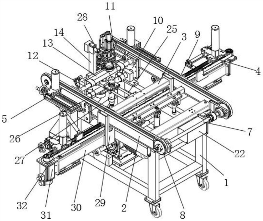
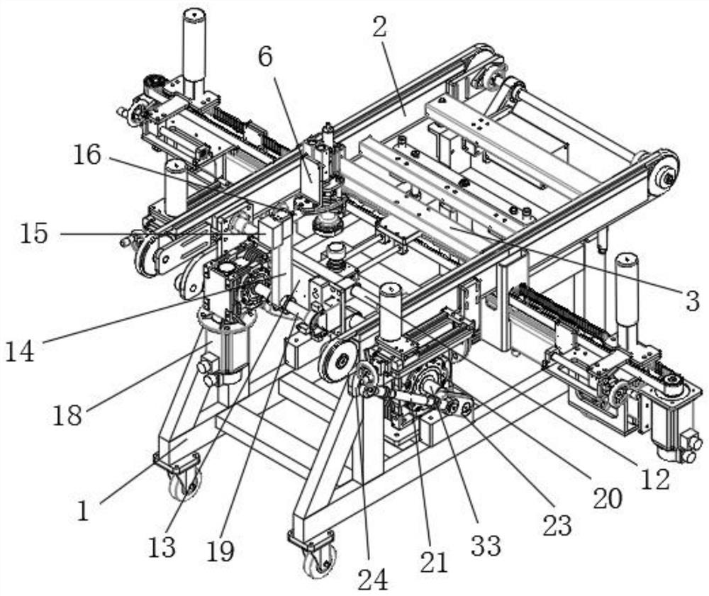
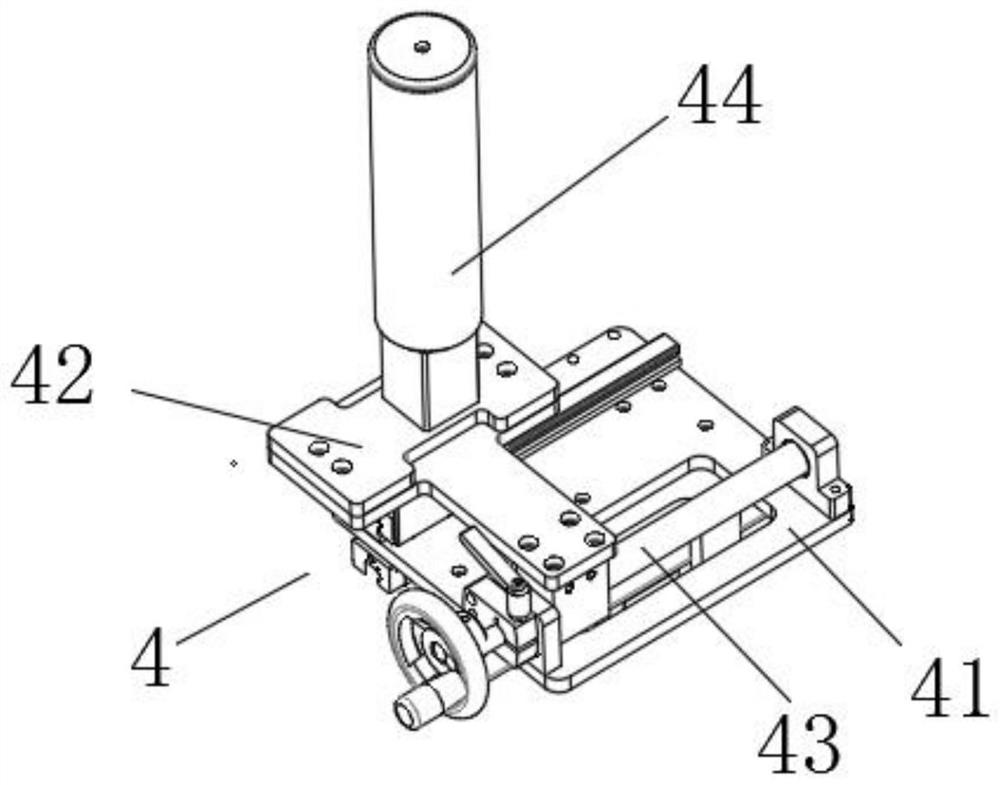
[0035] Such as Figure 1-5 As shown, a plate handling equipment for wall decoration includes a mobile base frame 1, and the top of the mobile base frame 1 is fixed with two conveying cross bars 2 by bolts, and the two conveying cross bars 2 Two fixed crossbars 3 are vertically arranged between them, and the two ends of the fixed crossbars 3 are respectively fixedly connected with the inner surfaces of the two fixed crossbars 3 by welding, and two fixed crossbars 3 are rotatably installed with two The first rotating shaft 7...


PUM


Abstract

The invention discloses plate carrying equipment for wall decoration, including a mobile chassis, two conveying cross rods are mounted at the top of the movable chassis; the two transmission wheels are in transmission connection through a conveying belt; a first limiting mechanism is movably mounted on the supporting side rod; second limiting mechanisms are installed on the outer side faces of thetwo conveying transverse rods, an output shaft of a rotary air cylinder is fixedly connected with one end of a connecting air cylinder, a suction plate mechanism is fixedly installed at the other endof the connecting air cylinder, an angle adjusting motor is fixedly installed at the bottom of the movable chassis, and one end of a second connecting rod is connected with a rotary shaft connectingplate. Decorative plates do not need to be lifted to the conveying belt, the labor intensity is greatly reduced, the positions of the decorative plates can be straightened, subsequent decoration of the decorative plates is facilitated, meanwhile, the stability of the decorative plates in the conveying process is guaranteed, the decorative plates can be rapidly installed, convenience and rapidnessare achieved, and the working efficiency is improved.

Description

technical field [0001] The invention relates to the technical field of decoration equipment, in particular to a sheet material handling equipment used for wall decoration. Background technique [0002] The patent document (CN210393574U) discloses a plate handling automation equipment. When the equipment is in use, the plate needs to be placed on the pallet, the lifting height is high, and the labor intensity is high. The plate is placed on the pallet without any mechanism. Fixing the boards cannot ensure the stability of the boards during the transportation process, the boards are easily damaged, and it is inconvenient to unload the boards, it is inconvenient to install and use the boards, and the work efficiency is low. Contents of the invention [0003] The object of the present invention is to provide a plate handling equipment for wall decoration, which drives the transmission shaft to rotate through the angle adjustment motor, and drives the rotating shaft connecting ...

Claims


Application Information

Patent Timeline
Patent Type & Authority Applications(China)
IPC IPC(8): B62B3/02B62B3/04B62B3/10E04G21/16
CPCB62B3/02B62B3/04B62B3/108B62B2202/62B62B2203/07B62B2203/60B62B2203/70E04G21/16
Inventor 张超左孝文王东东张弟袁紫薇
Owner 马鞍山观点信息科技股份有限公司
Why Eureka
Try Eureka