
Hydraulic dual-station clamp and working method thereof

A double-station, fixture technology, applied in the field of hydraulic fixtures, can solve the problems of low work efficiency of fixtures, inconvenient adjustment of fixtures, etc.

Active Publication Date: 2020-09-11
黄山市马勒机车部件有限公司
View PDF7 Cites 0 Cited by
  • Summary
  • Abstract
  • Description
  • Claims
  • Application Information

AI Technical Summary

Problems solved by technology

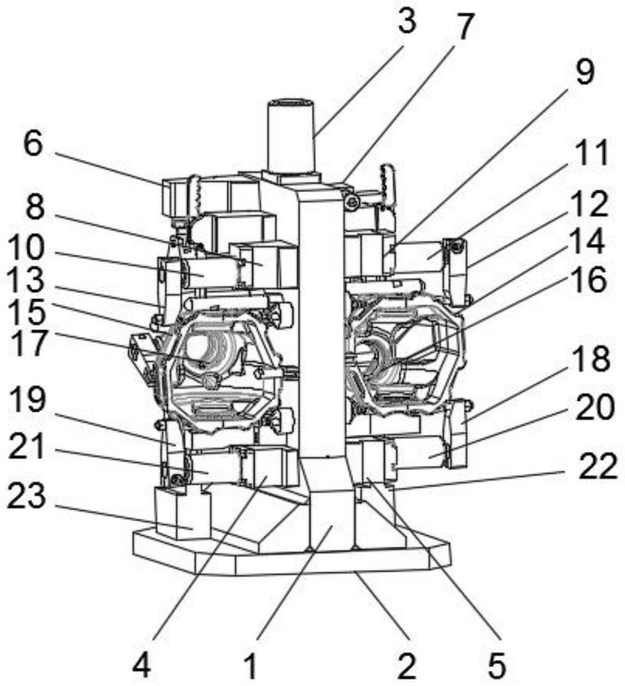
[0006] How to solve the problem of low working efficiency of the clamp and inconvenient adjustment of the clamp; in various aspects disclosed in the embodiments of the present invention, the speed of the connecting shaft is controlled through the reducer, and the clamping and clamping of the first clamp body and the second clamp body are controlled by a hydraulic cylinder. Loosening can realize the adjustment operation of the first fixture body and the second fixture body. The set first inner cavity and the second inner cavity play the role of limiting and storing the workpiece, and the fifth connection is controlled by the sixth fixed seat. The up and down rotation of the rotating column, the up and down rotation of the clamping seat is adjusted through the transmission column, the up and down rotation is performed through the second fixture body, and the up and down expansion and contraction of the lifting column is used to clamp and loosen the second fixture body by the clamping seat. When the second fixture body is loose, the second stopper and the fourth stopper rotate to the rear of the second fixture body, the second stopper rotates through the first connection rotating column and the third fixed seat, and the fourth stopper rotates through the fourth connection The rotation of the column and the first clamp seat can loosen and take out the workpiece in the second inner cavity. When the second clamp body is clamped, the second stopper and the fourth stopper rotate to the front of the second clamp body until The second stopper and the fourth stopper are in a vertical state, so that the workpiece in the second inner cavity is clamped, and the precise clamping of the hydraulic double-station fixture can be realized through the cooperation of the transmission column, the swivel and the clamping seat and loosening operation, the first fixture body can perform the same operation as the second fixture body at the same time, which can effectively improve the working efficiency of the hydraulic double-station fixture

Method used


Image

  • Hydraulic dual-station clamp and working method thereof
  • Hydraulic dual-station clamp and working method thereof
  • Hydraulic dual-station clamp and working method thereof

Examples


Embodiment 1

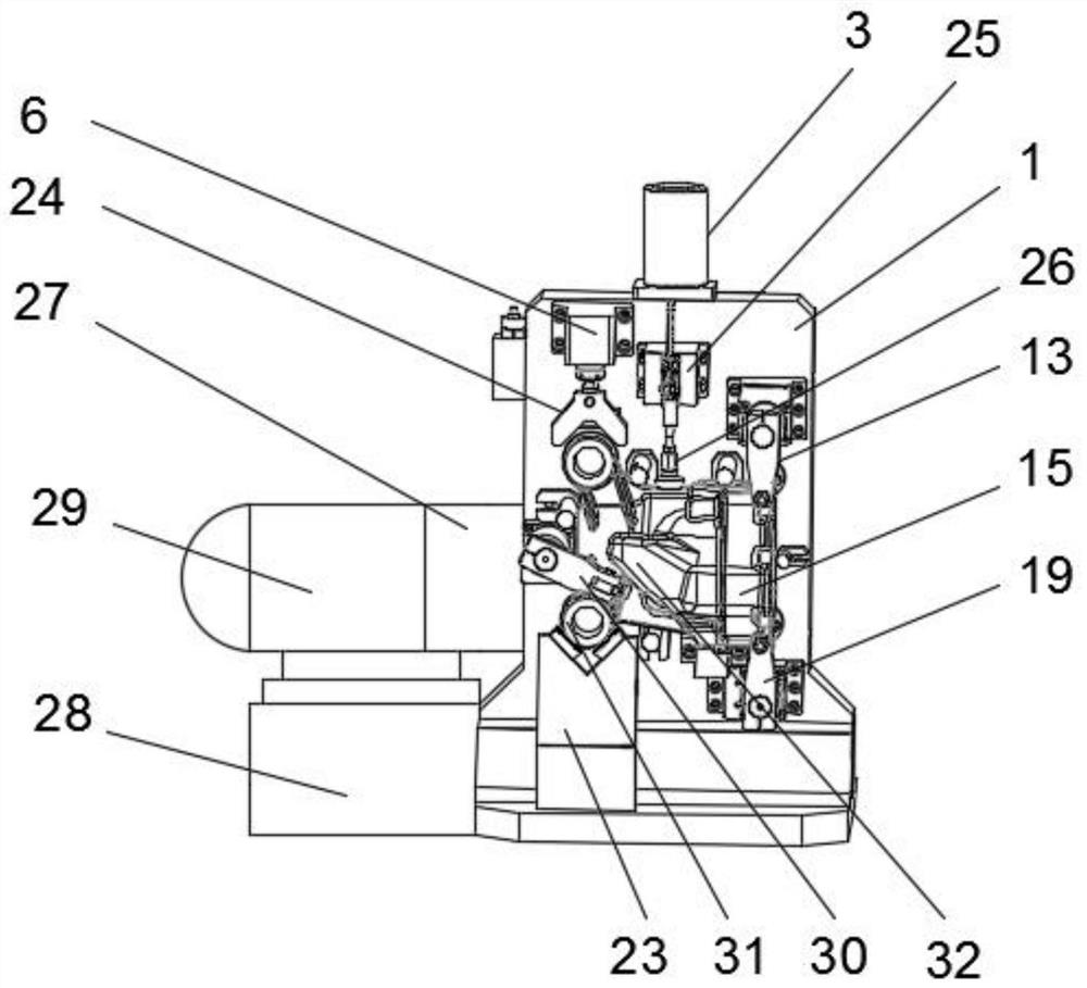
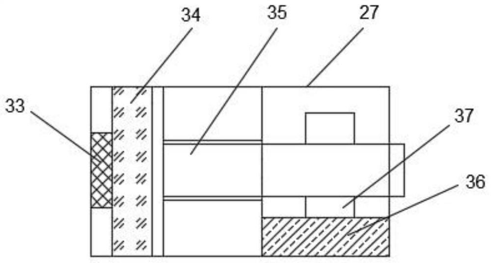
[0033] Such as Figure 1-4 As shown, a hydraulic double-station clamp includes a support plate 1, a first clamp body 14 and a second clamp body 15, and the first clamp body 14 and the second clamp body 15 are located on both sides of the support plate 1, so The lower end of the support plate 1 is equipped with a support base plate 2, and the rear end of the support plate 1 is connected to a transmission structure 27 and a servo motor 29 near the middle, and the transmission structure 27 is located between the servo motor 29 and the support plate 1. Position, the lower end of the servo motor 29 is equipped with a support base 28, the upper end of the support plate 1 is installed with a connecting column 3, the inside of the first clamp body 14 is provided with a first inner cavity 16, and the second clamp The inside of the main body 15 is provided with a second inner cavity 17, and one side of the support plate 1 is installed near the upper position with a first fixing seat 6, ...

Embodiment 2

[0049] The workpiece to be processed is placed in the first inner cavity 16 and the second inner cavity 17. The workpiece to be processed can be an automobile part, start the servo motor 29, control the speed of the connecting shaft 35 through the reducer 34, and use the hydraulic cylinder to control the first Clamping and loosening of the clamp body 14 and the second clamp body 15;

[0050] The up and down rotation of the fifth connecting rotating column 39 is controlled by the sixth fixed seat 38, the clamping seat 32 is clamped and loosened by the transmission column 30, the second clamp body 15 is rotated up and down, and the lifting column 26 is stretched up and down. Utilize the clamping seat 32 to clamp and loosen the second clamp body 15;

[0051] Wherein, when the second clamp body 15 is loose, the second stopper 13 and the fourth stopper 19 rotate to the rear of the second clamp body 15, the lifting column 26 moves downward, and the second stopper 13 passes through t...


PUM


Abstract

The invention discloses a hydraulic double-station clamp and a working method thereof. A first inner cavity and a second inner cavity are arranged for limiting and storing a workpiece; a sixth fixingseat is used for controlling upward and downward rotation of a fifth connecting rotating column; a drive column is used for adjusting the clamping and loosening of a clamping seat; the upward and downward rotation is performed through a second clamp body; through the upward and downward stretch of a lifting column, the second clamp body is clamped and loosened by utilizing the clamping seat; whenthe second clamp body is loosened, the workpiece in the second inner cavity is loosened and taken out; when the second clamp body is clamped until a second stopper and a fourth stopper are in a vertical state, the workpiece in the second inner cavity is clamped; through cooperative use of the drive column, a rotating ring and the clamping seat, accurate clamping and loosening operation of the hydraulic double-station clamp can be achieved, a first clamp body and the second clamp body can perform the same operation simultaneously, and the working efficiency of the hydraulic double-station clampcan be effectively improved.

Description

technical field [0001] The invention relates to the technical field of hydraulic clamps, in particular to a hydraulic double-station clamp and a working method thereof. Background technique [0002] At present, there are two main clamping methods, one is manual clamping using pneumatic wrench, screw, and pressing plate, and the other is automatic clamping using hydraulic cylinder to push up the workbench. The manual clamping method has low work efficiency and labor intensity. Large, a worker can only complete a dozen product tests per hour on average, and the clamping process takes up most of the time. Although the hydraulic clamping method has high work efficiency and causes environmental pollution, the continuous operation of the hydraulic pump causes noise pollution and energy waste. Although the pneumatic clamping method is efficient, energy-saving and environmentally friendly, the compressed air is easy to leak, the system working pressure is low, and the clamping force...

Claims


Application Information

Patent Timeline
Patent Type & Authority Applications(China)
IPC IPC(8): B25B11/00
CPCB25B11/00
Inventor 涂词添戴振海
Owner 黄山市马勒机车部件有限公司
Learn More