Fully automatic laser paint stripping recognition all-in-one machine

A laser paint stripping and fully automatic technology, which is applied in the direction of conveyors, conveyor objects, rotary conveyors, etc., can solve problems such as increased inspection costs, smaller and more precise component structures, and component alignment and grasping.

Active Publication Date: 2021-08-17
金动力智能科技(深圳)有限公司
View PDF8 Cites 0 Cited by
  • Summary
  • Abstract
  • Description
  • Claims
  • Application Information

AI Technical Summary

Problems solved by technology

[0002] The development of electronic components has gone through the process from large to small and from rough to precise, especially the development of electronic components such as resistors and capacitors. From the large size of the circular structure to the current overall structure, the maximum size of the components is no more than 5mm. The smaller and more precise structure also leads to the difficulty of production and testing, especially after the production of resistors or capacitors, the coating is easy, and the resistor or capacitor components are immersed in liquid paint, but after coating, it is necessary to Partial peeling of the paint, the resistance or capacitor components can have soldered terminals after the paint is peeled off. However, in the process of peeling the paint, it is unrealistic to rely on manual arrangement processing. A large number of components are laid on the table and passed through the industrial CCD camera It is also more troublesome, so it is not possible to accurately capture the components, and at the same time generate the corresponding position data and send it to the laser paint stripping device, one by one individually arranged for production, in the process of stripping the paint and then welding, in order to quickly batch Production, resulting in a decline in the yield of components or an increase in testing costs during the final production inspection, so the current processing equipment has problems such as low processing efficiency, troublesome operation, and inability to mass produce

Method used


Image

  • Fully automatic laser paint stripping recognition all-in-one machine
  • Fully automatic laser paint stripping recognition all-in-one machine
  • Fully automatic laser paint stripping recognition all-in-one machine

Examples


Embodiment 1

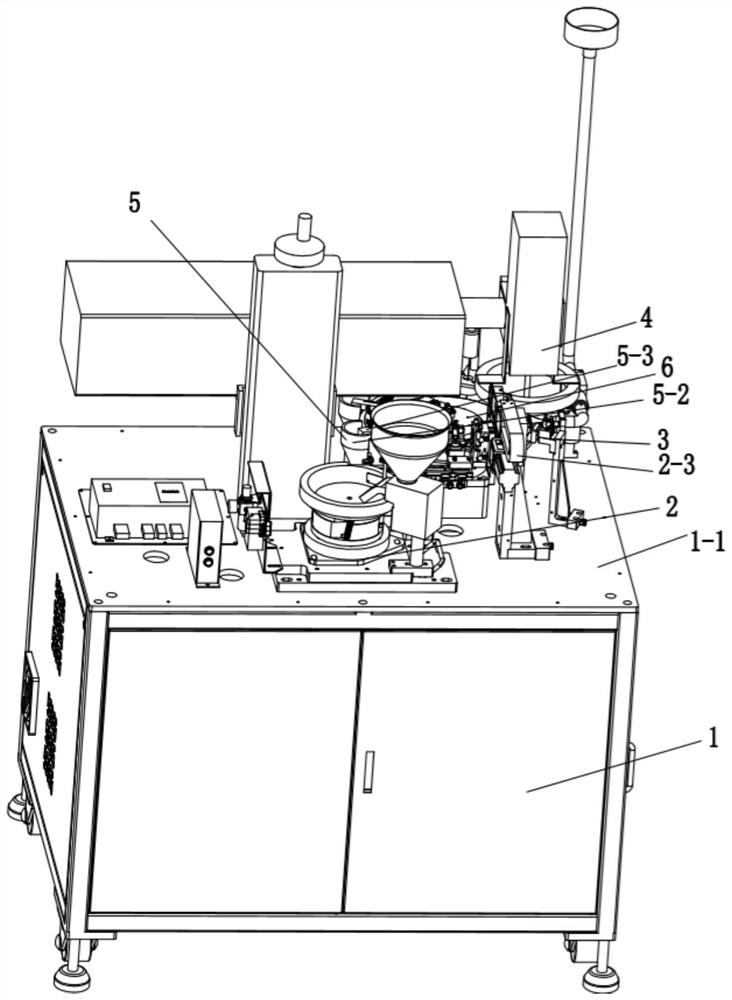
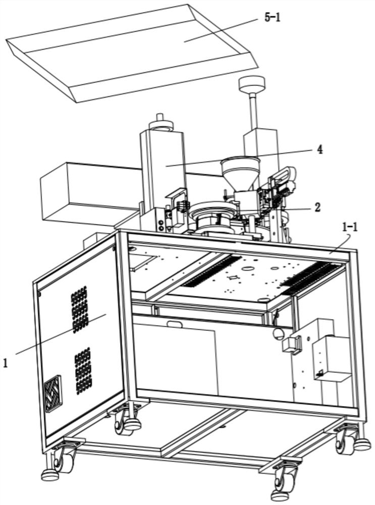
[0048] see Figure 1-18 , the present embodiment provides a fully automatic laser paint stripping recognition machine, comprising a frame 1, the following components are arranged on the table panel 1-1 of the frame 1:

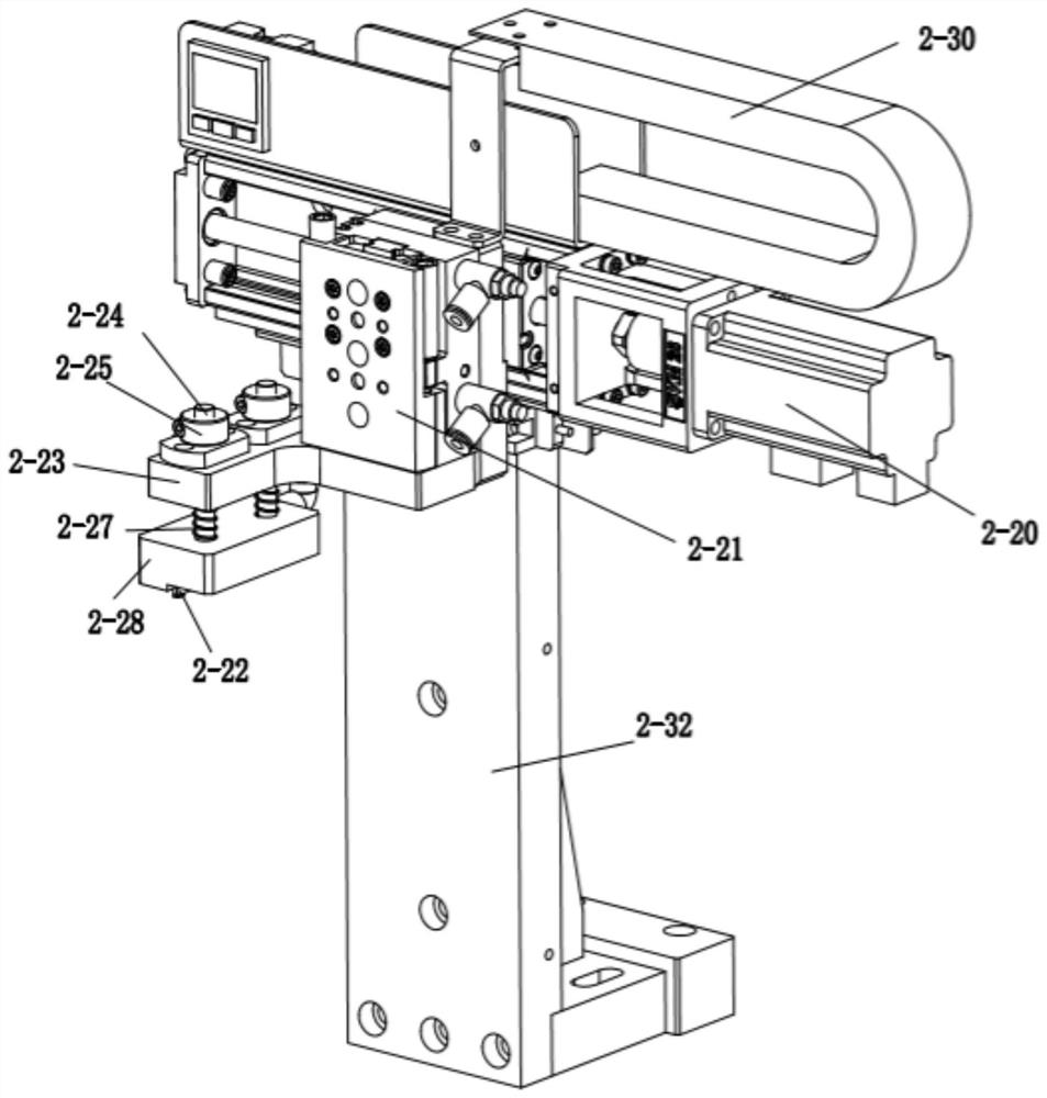
[0049] A vibrating plate feeding assembly 2 for loading and transporting components;

[0050] The separation component 3 that transfers the vibrating plate feeding component 2 and takes out the stacked components;

[0051] Paint stripping component 4 for stripping paint on the surface of the components after taking materials;

[0052] A receiving assembly 5 for collecting the components after the paint stripping assembly 4 is completed;

[0053] And a rotating assembly 6 for transferring components between the reclaiming station, the paint stripping station and the receiving station;

[0054] Wherein, the separation assembly 3 includes a dynamic separation assembly 3-1, and the dynamic separation assembly 3-1 includes a first fixed frame 3-2, a first cylinde...


PUM


Abstract

The invention discloses a full-automatic laser paint stripping and identification integrated machine, which includes a frame, and the following components are arranged on the table panel of the frame: a vibrating plate feeding assembly for loading and transporting components; The separation component for retrieving the accumulated components transferred from the tray loading component; the paint stripping component for stripping the paint on the surface of the components after retrieving; the receiving component for collecting the components after the paint stripping component is completed; And the rotating assembly that transfers the components between the unloading station, the paint stripping station and the receiving station. The invention realizes rapid mass production of production, and realizes the characteristics of automatic material picking, automatic material stripping and automatic material unloading.

Description

technical field [0001] The invention relates to resistance and capacitance production and manufacturing equipment, in particular to a full-automatic laser paint stripping and identification all-in-one machine. Background technique [0002] The development of electronic components has gone through the process from large to small and from rough to precise, especially the development of electronic components such as resistors and capacitors. From the large size of the circular structure to the current overall structure, the maximum size of the components is no more than 5mm. The smaller and more precise structure also leads to the difficulty of production and testing, especially after the production of resistors or capacitors, the coating is easy, and the resistor or capacitor components are immersed in liquid paint, but after coating, it is necessary to Partial peeling of the paint, the resistance or capacitor components can have soldered terminals after the paint is peeled of...

Claims


Application Information

Patent Timeline
Patent Type & Authority Patents(China)
IPC IPC(8): B08B7/00B08B13/00B07C5/02B07C5/34B07C5/36B65G29/00B65G47/26
CPCB07C5/02B07C5/34B07C5/365B08B7/0042B08B13/00B65G29/00B65G47/26
Inventor 姚伟涛夏欢张勇
Owner 金动力智能科技(深圳)有限公司
Why Eureka
Try Eureka