High-salinity sewage treatment equipment

A technology for treating equipment and high-salt sewage, which is applied in water/sewage treatment, heating water/sewage treatment, water/sludge/sewage treatment, etc. It can solve problems such as high operating costs, large investment, and difficulty in achieving purification effects

Pending Publication Date: 2022-02-01
陈廷炜
View PDF7 Cites 0 Cited by
  • Summary
  • Abstract
  • Description
  • Claims
  • Application Information

AI Technical Summary

Problems solved by technology

[0004] In order to overcome the use of biological methods, because high salinity will adversely affect the normal metabolism of microorganisms, and excessive salinity will inhibit the growth of microorganisms, the use of physical and chemical methods requires large investment and high operating costs, and it is difficult to achieve expectations. The purification effect is still the shortcoming of the focus of research at home and abroad. The technical problem to be solved is: to provide a high-salt sewage treatment equipment with small investment, fast filtration and automatic collection, fast evaporation and convenient scraping treatment

Method used


Image

  • High-salinity sewage treatment equipment
  • High-salinity sewage treatment equipment
  • High-salinity sewage treatment equipment

Examples


Embodiment 1

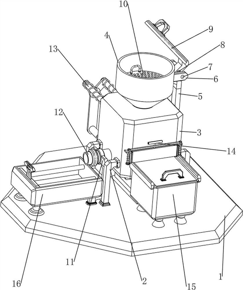
[0024] A high-salt sewage treatment equipment, such as Figure 1-4 As shown, it includes a base 1, a first bracket 2, a first shell 3, a feed hopper 4, a connecting block 5, a first fixing block 6, a first connecting rod 7, a first spring 8, a flip cover 9, and a filter plate 10 , the second support 11, the water pipe 12, the sewage pushing mechanism 13 and the opening and closing mechanism 14, the left and right sides of the middle right part on the base 1 are symmetrically provided with the first support 2, and the first support 2 is arranged between the tops of the four first support 2 A shell 3, the top of the first shell 3 is provided with a feed hopper 4, a connecting block 5 is provided between the right wall of the feed hopper 4 and the right wall of the first shell 3, and the upper part of the right wall of the feed hopper 4 is symmetrically provided with a first fixed Block 6, the first connecting rod 7 is arranged between the right sides of the two first fixed block...

Embodiment 2

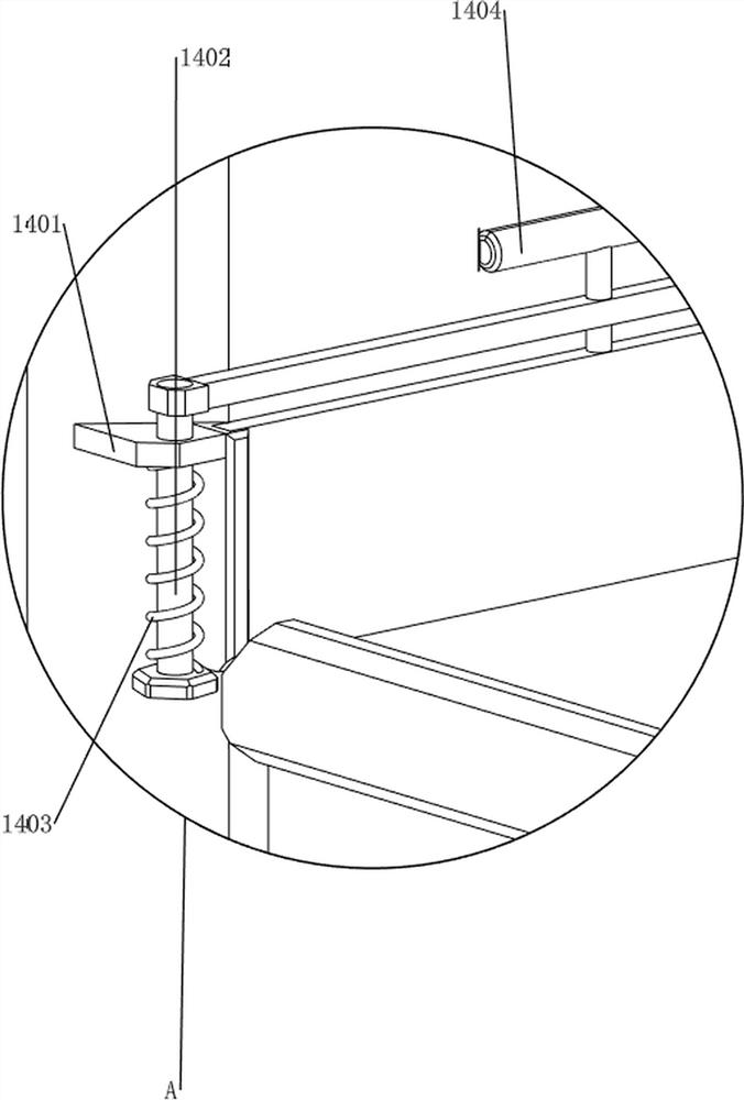
[0031] On the basis of Example 1, such as figure 1 , Figure 5 and Image 6 As shown, a collection mechanism 15 is also included, and the collection mechanism 15 includes a first support block 1501, a second housing 1502, a second fixed rod 1503, a fourth spring 1504, a second push rod 1505 and a slide block 1506, on the base 1 The front and rear of the right side of the front part are symmetrically provided with first support blocks 1501, and the tops of the four first support blocks 1501 are provided with second shells 1502. A second push rod 1505 is slidably arranged between the two second fixed rods 1503, and the front part of the second push rod 1505 is slidably connected with the second housing 1502, and a fourth spring 1504 is wound on the second fixed rod 1503. The two ends of the spring 1504 are respectively connected with the second fixed rod 1503 and the second push rod 1505 on the same side, and the rear end of the second push rod 1505 cooperates with the first p...


PUM


Abstract

The invention relates to sewage treatment equipment, and especially relates to high-salinity sewage treatment equipment. The high-salinity sewage treatment equipment provided by the invention has the advantages of small investment, rapid filtration, automatic collection, rapid evaporation and convenience in scraping treatment. The high-salt sewage treatment equipment comprises a base, first supports, a first shell, a feeding hopper, a connecting block, first fixing blocks and the like; and the first supports are symmetrically arranged on the left side and the right side of the middle right portion of the base, the first shell is arranged among the top ends of the four first supports, the feeding hopper is arranged on the top of the first shell, the connecting block is arranged between the right wall of the feeding hopper and the right wall of the first shell, and the first fixing blocks are symmetrically arranged on the upper portion of the right wall of the feeding hopper. By arranging a dirt pushing mechanism, an air cylinder telescopic rod retracts to drive a first push rod to move forwards, so that the first push rod moves forwards to push dirt and impurities out of the front side of the first shell, and the purpose of automatically pushing dirt is achieved.

Description

technical field [0001] The invention relates to sewage treatment equipment, in particular to high-salt sewage treatment equipment. Background technique [0002] High-salt wastewater refers to wastewater with a total salt content of at least 1%, which mainly comes from chemical plants, oil and natural gas collection and processing, etc. This wastewater contains a variety of substances (including salt, oil, organic heavy metals and radioactive substances). Salt wastewater is produced in a wide range of ways, and the amount of water is increasing year by year. Wastewater needs to be treated before it can be discharged. It is very important to remove the organic pollutants in the salty sewage that have an impact on the environment. Biological methods are used for treatment, because high salinity will have an adverse effect on the normal metabolism of microorganisms, and excessive salinity will inhibit the growth of microorganisms. The use of physical and chemical methods requir...

Claims


Application Information

Patent Timeline
Patent Type & Authority Applications(China)
IPC IPC(8): C02F1/04B08B9/087C02F101/10
CPCC02F1/048C02F1/043B08B9/087C02F2303/14C02F2101/10
Inventor 陈廷炜
Owner 陈廷炜
Why Eureka
Try Eureka