
Wireless transceiving equipment powered by intrinsically safe power supply for mine

A technology of wireless transceiver equipment and intrinsically safe power supply, which is applied to conversion equipment, electrical components, and transmission systems with intermediate conversion to AC, and can solve the problem of increasing wireless transmission distance, increasing the negative electrode area of ​​antennas, and wireless transceiver equipment cannot meet Problems such as insulation resistance and power frequency withstand voltage, to achieve the effect of increasing wireless transmission distance and ingenious architecture design

Active Publication Date: 2020-09-08
重庆弘域达科技有限责任公司
View PDF8 Cites 0 Cited by
  • Summary
  • Abstract
  • Description
  • Claims
  • Application Information

AI Technical Summary

Problems solved by technology

In addition, for wireless transceiver equipment powered by intrinsically safe output power (referred to as intrinsically safe power supply), in order to ensure that the equipment can work normally as far as possible, the wireless transceiver power is usually limited. In this case, the negative pole of the antenna is connected to the metal shell of the wireless transceiver device, and the area of ​​the negative pole of the antenna is increased, which can effectively increase the distance of wireless transmission. Requirements for insulation resistance and power frequency withstand voltage

Method used


Image

  • Wireless transceiving equipment powered by intrinsically safe power supply for mine
  • Wireless transceiving equipment powered by intrinsically safe power supply for mine
  • Wireless transceiving equipment powered by intrinsically safe power supply for mine

Examples


Embodiment 1

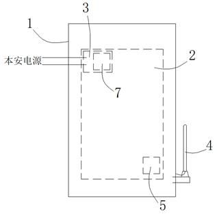
[0022] Embodiment 1: as figure 1 As shown, a wireless transceiver device powered by an intrinsically safe power supply for mines includes a metal casing 1 and a main control module 2 protected inside the metal casing 1, and the main control module 2 includes a The power block 3 of the intrinsically safe power supply and the wireless transceiver module 5 for receiving or sending wireless signals; the outside of the metal casing 1 is also provided with an antenna 4, and the negative pole of the antenna 4 is electrically connected to the metal casing 1, The power block 3 is provided with an isolation converter 7 capable of forming a physical isolation from the power input end. Specifically, the isolation converter 7 includes an isolation transformer for realizing physical isolation.

[0023] With the above structure, the negative pole of the antenna is connected to the metal shell, so that the transmission distance of the wireless signal can be increased. Physical isolation, so...

Embodiment 2

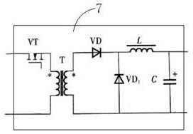
[0025] Embodiment 2: The difference from Embodiment 1 is that in this embodiment, the isolated converter 7 is an isolated Buck-Boost flyback converter, such as image 3 shown.

Embodiment 3

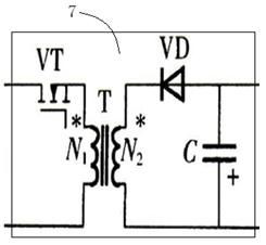
[0026] Embodiment 3: The difference from Embodiment 1 is that in this embodiment, the isolated converter 7 is an isolated Flyback flyback converter, such as Figure 4 shown.


PUM


Abstract

The invention discloses wireless transceiving equipment powered by an intrinsically safe power supply for a mine. The wireless transceiving equipment comprises a power supply block used for being connected with the intrinsically safe power supply and a wireless transceiving module used for receiving or sending a wireless signal, the mobile terminal is characterized in that the mobile terminal further comprises a metal shell and an antenna arranged outside the metal shell, and the negative electrode of the antenna is electrically connected to the metal shell; and a high-voltage capacitor is connected in series between the metal shell and the wireless transceiver module and / or the power supply block is provided with an isolation converter capable of forming physical isolation with an input power supply. The wireless transceiving equipment has the advantages of ingenious architecture design, capability of increasing the wireless transmission distance under the condition of meeting the requirements of insulation resistance and power frequency withstand voltage, and the like.

Description

technical field [0001] The invention relates to the technical field of mine safety equipment, in particular to a wireless transceiver equipment powered by an intrinsically safe power supply for mines. Background technique [0002] In recent years, with the development and application of wireless transmission technology, more and more wireless devices have been used in mine operations. Wireless transceiver equipment belongs to mine electrical equipment, which needs to meet the insulation resistance and power frequency resistance specified in "MT 210-1990". pressure requirements. In addition, for wireless transceiver equipment powered by intrinsically safe output power (referred to as intrinsically safe power supply), in order to ensure that the equipment can work normally as far as possible, the wireless transceiver power is usually limited. In this case, connecting the negative pole of the antenna to the metal case of the wireless transceiver device, increasing the area of ...

Claims


Application Information

Patent Timeline
Patent Type & Authority Applications(China)
IPC IPC(8): H04B1/38H02M3/28
CPCH04B1/38H02M3/28
Inventor 程绍缘李炜陈均
Owner 重庆弘域达科技有限责任公司
Learn More