Wall drainage closestool drainage structure and mounting method thereof
A technology of drainage structure and installation method, which is applied in water supply devices, flushing toilets, flushing equipment with water tanks, etc., can solve problems such as difficult dredging, and achieve the effect of easy dredging and normal use
- Summary
- Abstract
- Description
- Claims
- Application Information
AI Technical Summary
Problems solved by technology
Method used
Image
Examples
Embodiment 1
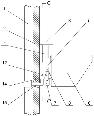
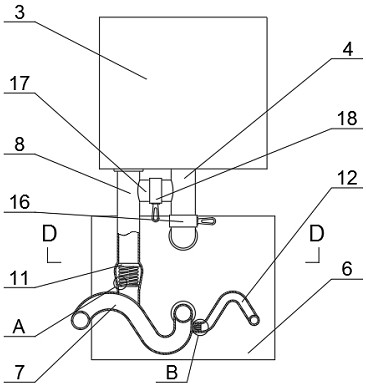
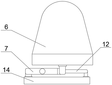
[0028] Embodiment one, with reference to Figure 1-5 , a wall toilet drainage structure, comprising an installation wall 2, a sewage main pipe 1 installed inside the installation wall 2, a water tank 3 installed at the outer end of the installation wall 2, a flushing elbow 4 installed at the lower end of the water tank 3, installed on the installation wall The toilet hanging screw 5 at the outer end of the wall 2 and the toilet 6 screwed and connected with the toilet hanging screw 5, the free end of the flushing elbow 4 is connected with the toilet 6, and the lower end of the water tank 3 is installed on one side of the flushing elbow 4 There is a side pipe 8, a connecting pipe 17 is installed between the side pipe 8 and the flushing elbow 4, and the connecting pipe 17 is connected to the side pipe 8 and the flushing elbow 4, and the rear end of the toilet 6 is installed with a sewage elbow 7, And the free end of side pipe 8 is connected with blowdown elbow 7, and branch pipe ...
Embodiment 2
[0029] Embodiment two, refer to figure 2 , a wall-mounted toilet drainage structure, a first control valve 16 is installed on the outside of the flush elbow 4, a second control valve 18 is installed on the outside of the connecting pipe 17, and the first control valve 16 and the second control valve 18 are arranged It is convenient for the user to control the water connection and closure of the flush water elbow 4 and the connecting pipe 17 .
Embodiment 3
[0030] Embodiment three, refer to figure 2 , Figure 4 and Figure 5 , a wall-mounted toilet drainage structure, a ring plate 9 is installed on the side of the side pipe 8 close to the sewage elbow 7, and a check valve 11 is slidingly embedded in the inside of the side pipe 8, and the check valve 11 is connected to the ring plate 9 There is an extrusion spring 10 between them, and the first end of the extrusion spring 10 is fixedly connected to the ring plate 9, the second end of the extrusion spring 10 is fixedly connected to the one-way valve 11, and the inner end of the branch pipe 12 is close to the sewage elbow One side of 7 is equipped with annularly distributed resistance blocks 13, and the setting of one-way valve 11 helps to control the one-way discharge of flushing water. The side pipe 8 is arranged on one side of the upper bend of sewage elbow 7, Thereby, it is convenient for the flushing water to loosen the clog at the sewage trap 7, and the setting of the block...
PUM
 Abstract
Description
Claims
Application Information
 - R&D
- Intellectual Property
- Life Sciences
- Materials
- Tech Scout
- Unparalleled Data Quality
- Higher Quality Content
- 60% Fewer Hallucinations
Browse by: Latest US Patents, China's latest patents, Technical Efficacy Thesaurus, Application Domain, Technology Topic, Popular Technical Reports.
© 2025 PatSnap. All rights reserved.Legal|Privacy policy|Modern Slavery Act Transparency Statement|Sitemap|About US| Contact US: help@patsnap.com


