Novel water stop structure for preventing permanent joint of concrete dam from leaking water

A concrete dam, permanent technology, applied in water conservancy engineering, marine engineering, construction and other directions, can solve problems such as hidden dangers of engineering, submerged observation instruments, maintenance and plugging difficulties, etc., to prevent water leakage, convenient construction, and low cost.

Pending Publication Date: 2020-09-08
DALIAN UNIV OF TECH
View PDF0 Cites 0 Cited by
  • Summary
  • Abstract
  • Description
  • Claims
  • Application Information

AI Technical Summary

Problems solved by technology

[0002] Concrete dams often have copper waterstops between the permanent structural joints, one for middle and low dams, and two or even three waterstops for high dams. However, since copper waterstops and concrete are different materials, it is difficult to shrink and deform. Consistent, there is the problem of uncoordinated deformation, and because the concrete has the problem of dry shrinkage and autogenous volume deformation, shrinkage deformation joints are often formed between the copper sheet waterstop and concrete. Under the action of reservoir water pressure hydraulic splitting, the copper sheet The shrinkage deformation joint between the water stop and the concrete gradually expands until it penetrates, and the reservoir water leaks out along the penetration joint and is exposed behind the dam, which brings hidden dangers to the project
Especially when there are traffic and observation corridors in the dam, water seeps through the corridors, causing the corridors to be filled with water. First, the observation instruments are submerged, causing the instruments to fail. Second, it is difficult to carry out the normal operation and management of the dam. Third, it is maintenance Plugging is very difficult, and the cost is high, and the construction is difficult

Method used


Image

  • Novel water stop structure for preventing permanent joint of concrete dam from leaking water
  • Novel water stop structure for preventing permanent joint of concrete dam from leaking water

Examples


Embodiment Construction

[0010] Below in conjunction with accompanying drawing and specific embodiment the present invention is described in further detail:

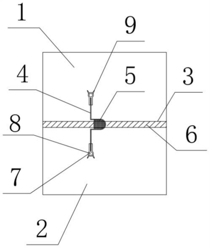
[0011] Such as figure 1 and figure 2 As shown, a new type of water-stop structure to prevent water leakage from the permanent joints of concrete dams, there is a permanent joint 3 between the first dam section 1 and the first dam section 2, and a high-pressure closed-hole plate 6 is set between the permanent joints 3; The convex water-stop copper sheet 4 is set, the boss of the water-stop copper sheet 4 is located at the span permanent joint 3, and the asphalt linoleum 5 is arranged inside it, and the two ends of the water-stop copper sheet 4 are buried in the first dam section 1 and the first dam section respectively. Between the dam sections 2, an inflatable "spherical" water-stop structure 7 is arranged at both ends of the water-stop copper sheet 4, and an inflatable cavity 8 is arranged inside the inflatable "spherical" water-stop structur...


PUM

PropertyMeasurementUnit
Lengthaaaaaaaaaa
Heightaaaaaaaaaa
Thicknessaaaaaaaaaa

Abstract

The invention discloses a novel water stop structure for preventing a permanent joint of a concrete dam from leaking water. The novel water stop structure comprises a high-pressure hole closing platearranged in the permanent joint between dam sections, a copper seal is arranged across the permanent joint, an asphalt hemp rope is arranged in a copper nose of the copper seal, the two ends of the copper seal are embedded into the dam sections on the two sides respectively, inflatable spherical water stops are arranged at the two ends of the copper seal, and each inflatable spherical water stop is provided with an inflatable cavity and an anti-seepage reinforcing plate. According to the structure, the inflatable spherical water stops and the anti-seepage reinforcing plates are arranged at theends of the copper seal, when concrete shrinks, the structure adapts to deformation, the purpose of sealing the joint to stop water can be achieved by inflating and pressing shrinkage joints betweenthe spherical water stops and the concrete, construction is convenient, the manufacturing cost is low, and the problem that the permanent joint leaks water can be effectively solved.

Description

technical field [0001] The invention is a novel water-stop structure for preventing water leakage from permanent joints of concrete dams. Background technique [0002] Concrete dams often have copper waterstops between the permanent structural joints, one for middle and low dams, and two or even three waterstops for high dams. However, since copper waterstops and concrete are different materials, it is difficult to shrink and deform. Consistent, there is the problem of uncoordinated deformation, and because the concrete has the problem of dry shrinkage and autogenous volume deformation, shrinkage deformation joints are often formed between the copper sheet waterstop and concrete. Under the action of reservoir water pressure hydraulic splitting, the copper sheet The shrinkage deformation joint between the water stop and the concrete gradually expanded until it penetrated, and the reservoir water leaked out along the penetration joint and exposed behind the dam, which brought ...

Claims


Application Information

Patent Timeline
IPC IPC(8): E02B3/16
CPCE02B3/16
Inventor 康飞王一帆
Owner DALIAN UNIV OF TECH
Why Eureka
Try Eureka