Oil sludge recycling system and method
A technology for oil sludge and oil wells, which is applied in the field of oil sludge recovery and utilization systems, can solve the problems of many sludge generation points, time-consuming and laborious collection and transfer process, and a wide range of areas, so as to save processing time and costs, reduce safety and environmental risks, and reduce processing costs Effect
- Summary
- Abstract
- Description
- Claims
- Application Information
AI Technical Summary
Problems solved by technology
Method used
Image
Examples
Embodiment 1
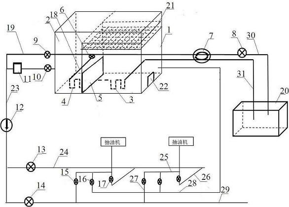
[0034] The present invention provides an oil sludge recycling system, comprising a treatment tank, the treatment tank is respectively connected to a mixing pipeline 29 and a hot washing pipeline 24 through an oil discharge pipeline 23, the treatment tank is connected to a heating mechanism, and the mixing pipeline 29 is connected to Crude oil metering transfer station, the hot washing pipeline 24 is connected to the oil well pipeline, and the oil discharge pipeline 23, the mixing pipeline 29 and the hot washing pipeline 24 are all provided with valves.
[0035] The present invention recovers the oil in the oil sludge through the treatment tank, and the recovered oil can enter the crude oil metering transfer station through the oil discharge pipeline 23 through the mixing pipeline 29, and can also pass the oil discharge pipeline 23 through the hot washing pipeline 24 to the oil well or pipeline Perform a hot wash.
[0036] The oil sludge recovery and utilization system provided...
Embodiment 2
[0038] On the basis of Example 1, the present invention provides a sludge recovery and utilization system, the treatment tank includes a settling part 1 and an overflow part 2, and the settling part 1 and the overflow part are separated by an overflow plate 5 Open, the top of the settling part 1 is provided with a filter screen 21, the lower side of the settling part 1 is provided with a waste sludge outlet 22, the oil discharge pipeline 23 communicates with the overflow part 2, and the oil discharge pipeline 23 is provided with There are oil discharge valve 10, centrifugal pump 11 and check valve 12.
[0039]The treatment tank is divided into left and right parts by an overflow plate 5 , namely a settling part 1 and an overflow part 2 . The process of recovering oil is as follows: the oil sludge is poured into or passed through the treatment tank. First, the oil sludge passes through the filter screen 21 arranged above the overflow part 2. The filter screen 21 filters large p...
Embodiment 3
[0042] On the basis of Embodiment 1, the present invention provides a kind of sludge recycling system, the heating mechanism includes a heating furnace 20, a heating furnace water outlet pipeline 30, a heating furnace return water pipeline 31 and a heating coil, the heating coil Set in the treatment tank, the two ends of the heating coil are connected with the heating furnace water outlet pipeline 30 and the heating furnace return water pipeline 31 respectively, and the heating furnace outlet water pipeline 30 is provided with a heating furnace outlet valve 8 and a circulating pump 7 .
[0043] In this embodiment, the existing heating furnace 20 at the well site is used. The hot water in the heating furnace 20 circulates in the coil, on the one hand, the purpose of heating the oil sludge is achieved, and the separation of oil and mud is better realized; After the oil phase is heated, the oil well or pipeline is hot-washed and wax-removed.
[0044] The hot washing pipeline 24 i...
PUM
 Abstract
Description
Claims
Application Information
 - R&D Engineer
- R&D Manager
- IP Professional
- Industry Leading Data Capabilities
- Powerful AI technology
- Patent DNA Extraction
Browse by: Latest US Patents, China's latest patents, Technical Efficacy Thesaurus, Application Domain, Technology Topic, Popular Technical Reports.
© 2024 PatSnap. All rights reserved.Legal|Privacy policy|Modern Slavery Act Transparency Statement|Sitemap|About US| Contact US: help@patsnap.com


