Medical-use tablet grinding equipment
A technology for medical use and tablets, applied in the field of medical tablet grinding equipment, can solve problems such as low grinding efficiency and achieve the effect of improving grinding efficiency
- Summary
- Abstract
- Description
- Claims
- Application Information
AI Technical Summary
Problems solved by technology
Method used
Image
Examples
Embodiment 1
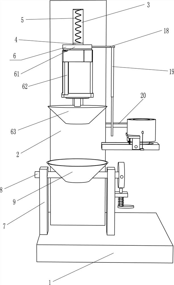
[0024] A medical tablet grinding equipment, such as figure 1 and figure 2 As shown, it includes a bottom plate 1, a vertical plate 2, a first slider 4, a first spring 5, a grinding mechanism 6, a fixed plate 7, a rotating rod 8 and a holding plate 9, and the top rear side of the bottom plate 1 is equipped with a vertical plate 2 , the upper part of the front wall of the riser 2 is provided with a first chute 3, and a first slider 4 is slidably provided in the first chute 3, and a first spring is fixedly connected between the top of the first slider 4 and the riser 2 5. The front wall of the first slider 4 is provided with a grinding mechanism 6, and the bottom plate 1 on the front side of the vertical plate 2 is provided with two fixed plates 7, and the upper part of the fixed plate 7 is provided with a rotating rod 8, and the two rotating rods Holding dish 9 is installed between 8.
[0025] Such as figure 1 As shown, the grinding mechanism 6 includes a mounting plate 61, ...
Embodiment 2
[0029] On the basis of Example 1, such as figure 2 Shown, also comprise fixed pulley 11, the second slide block 13, the second spring 14, pedal 15, wire conduit 16 and first stay cord 17, the middle part of riser 2 has opening 10, the inner wall of opening 10 A fixed pulley 11 is arranged on the top, and a second chute 12 is provided on the lower part of the rear wall of the riser 2, and a second slider 13 is slidably provided in the second chute 12, and the bottom of the second slider 13 and the riser 2 are fixed. The second spring 14 is connected, the second slide block 13 is equipped with a pedal 15, the vertical plate 2 on the lower side of the first chute 3 is embedded with a wire conduit 16, and the vertical plate 2 on the upper side of the second chute 12 is Wire conduit 16 is also embedded, and first stay cord 17 is fixedly connected on the first slide block 4, and first stay cord 17 passes upper side wire conduit 16 and walks around fixed pulley 11, and first stay co...
Embodiment 3
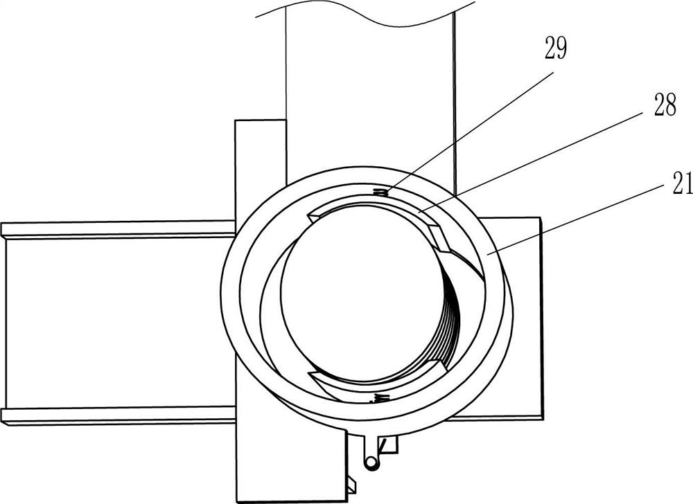
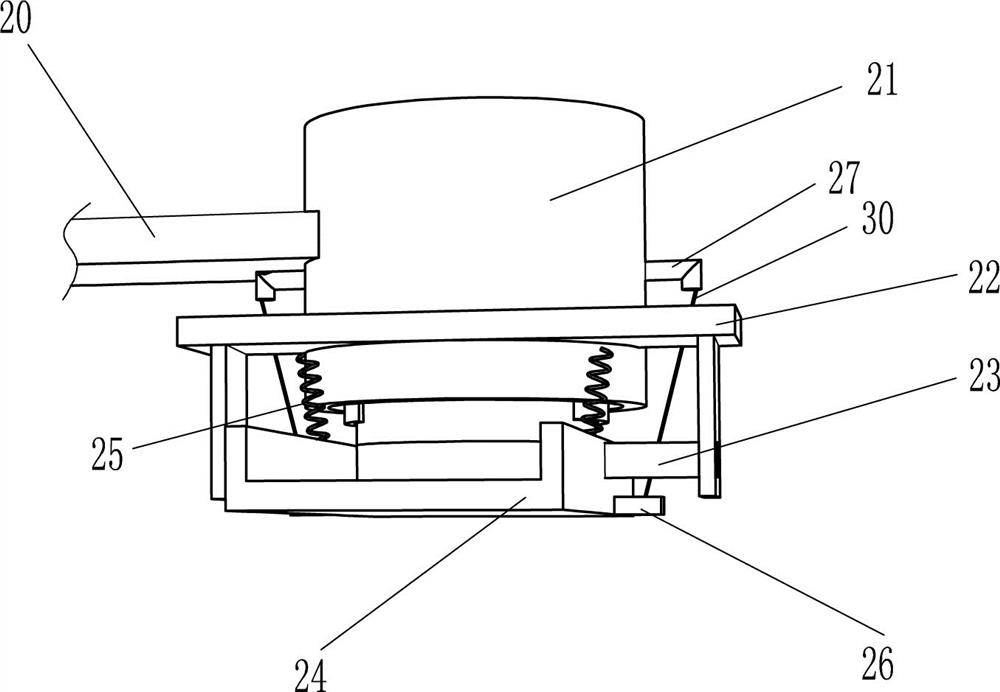
[0032] On the basis of Example 2, such as figure 1 , image 3 and Figure 4 Shown, also include the first connecting plate 18, telescoping rod 19, L-shaped plate 20, feeding tube 21, the second connecting plate 22, rotating shaft 23, cutting trough plate 24, the 3rd spring 25, connecting block 26, Conduit 27, arc-shaped plate 28, fourth spring 29 and second stay cord 30, the first connecting plate 18 is arranged on the right wall of mounting plate 61, is fixedly connected with telescopic rod 19 on the first connecting plate 18, riser 2 An L-shaped plate 20 is installed in the middle of the right wall of the L-shaped plate 20. The right part of the L-shaped plate 20 is provided with a feeding pipe 21. The left side of the lower part of the feeding pipe 21 is provided with a second connecting plate 22. The front and rear sides of the second connecting plate 22 bottom Both rotating shafts 23 are installed, between the two rotating shafts 23, a blanking chute plate 24 is install...
PUM
 Abstract
Description
Claims
Application Information
 - R&D Engineer
- R&D Manager
- IP Professional
- Industry Leading Data Capabilities
- Powerful AI technology
- Patent DNA Extraction
Browse by: Latest US Patents, China's latest patents, Technical Efficacy Thesaurus, Application Domain, Technology Topic, Popular Technical Reports.
© 2024 PatSnap. All rights reserved.Legal|Privacy policy|Modern Slavery Act Transparency Statement|Sitemap|About US| Contact US: help@patsnap.com


