Electrical connector

A technology for electrical connectors and riveting, which is applied in the direction of connection, two-part connection devices, parts of connection devices, etc. It can solve problems such as leakage of solid material holes, difficulty in reproducing signal transmission characteristics of electrical connectors, and increased production costs.

Active Publication Date: 2020-09-04
APTIV TECH LTD
View PDF5 Cites 0 Cited by
  • Summary
  • Abstract
  • Description
  • Claims
  • Application Information

AI Technical Summary

Problems solved by technology

[0008] Also, if the electrical leads are embedded in a solid insulating material, the solid material may seep through the pores
Because this leakage of solid insulating material cannot be controlled or can only be controlled to a certain extent, the signal transmission characteristics of electrical connectors are difficult to reproduce
[0009] Therefore, in order to make the holes as small as possible, complex bending or deep drawing techniques are required, resulting in a huge increase in production costs
However, this complex bending or deep-drawing technique was abandoned due to production cost and sacrificed sufficient shielding and signal integrity (i.e. good signal-to-noise ratio and minimal jitter of the transmitted signal)
[0010] Furthermore, with prior art electrical connectors, it is quite cumbersome to repeatedly arrange the components of the electrical connector (ie, basically at least one electrical lead, tunnel, insulating material and housing) so that each of the electrical connectors Each section includes the best impedance match or impedance mismatch is kept to a minimum

Method used


Image

  • Electrical connector
  • Electrical connector
  • Electrical connector

Examples


Embodiment Construction

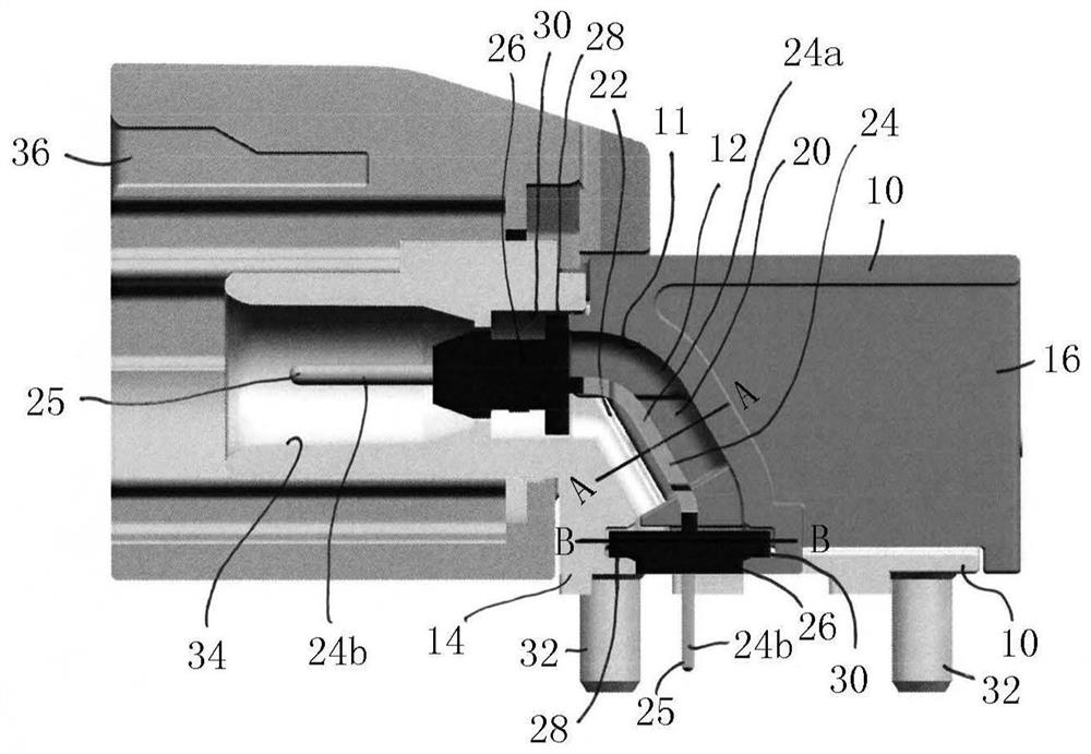
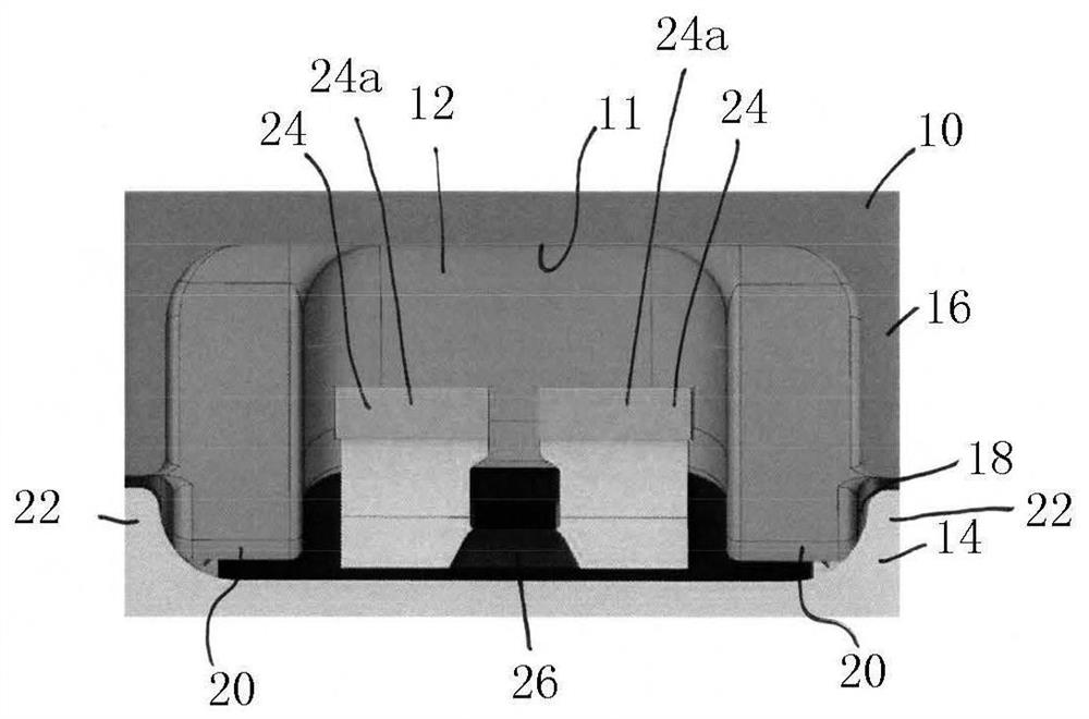
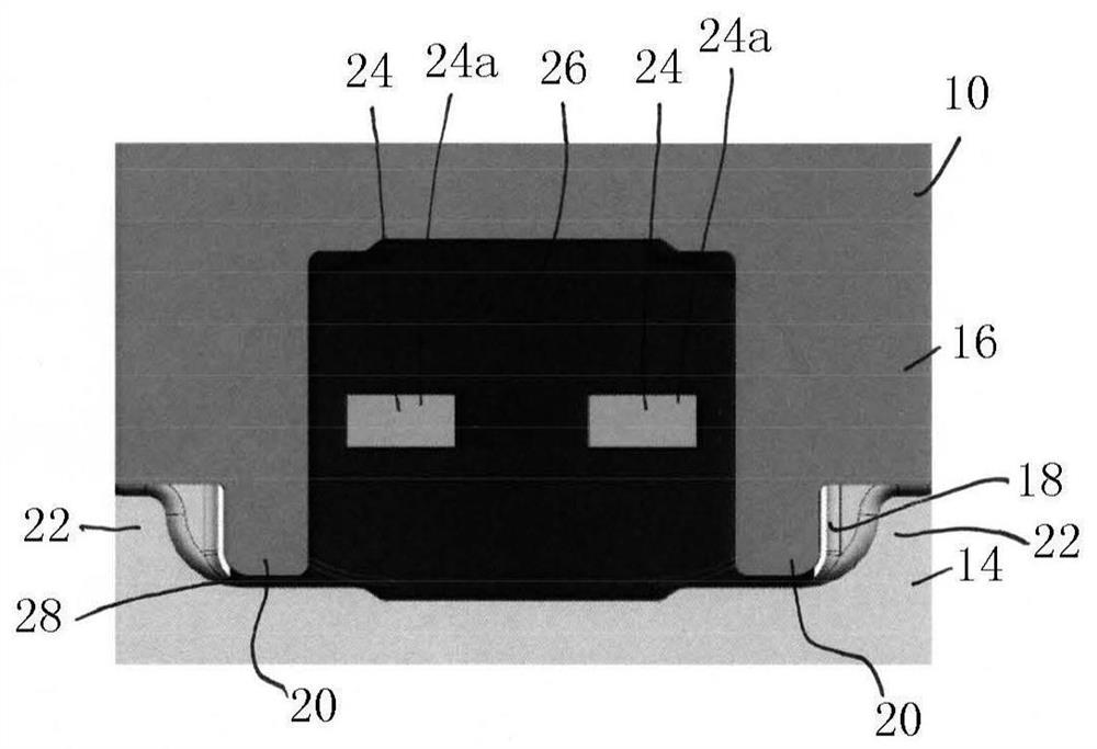
[0080] Figures 1 to 3d It relates to a first design of an electrical connector for high frequency data signal transmission. Figure 4 An electrical connector according to a second design is shown. Figure 5 to Figure 7b A third design concerns the electrical contact element.

[0081] figure 1 A longitudinal sectional view of an electrical connector for high-frequency data signal transmission is shown. The electrical connector includes a housing 10 having a tunnel 12 extending therethrough. Furthermore, housing 10 includes: a base 14 defining a first portion of tunnel 12 ; and a cover 16 defining a second portion of tunnel 12 . Thus, in the assembled state of the housing 10 , the base 14 and the cover 16 together form the tunnel 12 .

[0082] In order to provide good shielding properties of the housing 10, the cover 16 is tightly riveted to the base 14, as will be described in detail below. Furthermore, although not shown in the drawings for better illustration, the cove...


PUM


Abstract

The invention is directed to an electrical connector for high frequency data signal transmission comprising a housing, at least one tunnel extending through the housing and at least one electrical lead extending through the at least one tunnel, wherein, in the at least one tunnel, at least a portion of the electrical lead is embedded in a surrounding material having a relative permittivity which is less than 2.

Description

technical field [0001] The invention relates to an electrical connector for high-frequency data signal transmission, which comprises a housing, at least one tunnel extending through the housing, and at least one electrical lead extending through the tunnel. Background technique [0002] Such electrical connectors, which may also be referred to as pin headers, are well known in the art and are commonly used to transmit signals at high data rates, such as data rates between 1 GHz and 100 GHz. The signal is transmitted via at least one electrical lead, preferably made of an electrically conductive material such as a metallic material. [0003] Adequate shielding of the transmitted signal against external electromagnetic fields is an important issue for high data rate applications to avoid, or at least minimize, any interference with the transmitted signal by external electromagnetic fields. In particular, external electromagnetic fields may alter signals transmitted via unshie...

Claims


Application Information

Patent Timeline
Patent Type & Authority Applications(China)
IPC IPC(8): H01R13/6477H01R13/6581H01R13/502H01R13/504H01R24/00H01R43/00H01R43/20
CPCH01R13/6477H01R13/6581H01R13/502H01R13/504H01R24/00H01R43/00H01R43/20H01R24/50H01R12/724H01R13/514H01R43/18H01R13/405H01R13/6588H01R43/24
Inventor 格特·德勒施贝克J·伦福特
Owner APTIV TECH LTD
Why Eureka
Try Eureka