Measuring tip

A technology of measuring head and measuring unit, applied in the field of measuring head, can solve problems such as infeasibility and time-consuming

Inactive Publication Date: 2015-10-14
ROSENBERGER HOCHFREQUENZTECHNIK GMBH & CO KG
View PDF6 Cites 0 Cited by
  • Summary
  • Abstract
  • Description
  • Claims
  • Application Information

AI Technical Summary

Problems solved by technology

Furthermore, when the measuring conductor wears out, the entire measuring head needs to be replaced, since replacing only the measuring conductor is neither feasible nor proportionally time-consuming

Method used


Image

  • Measuring tip
  • Measuring tip
  • Measuring tip

Examples


Embodiment Construction

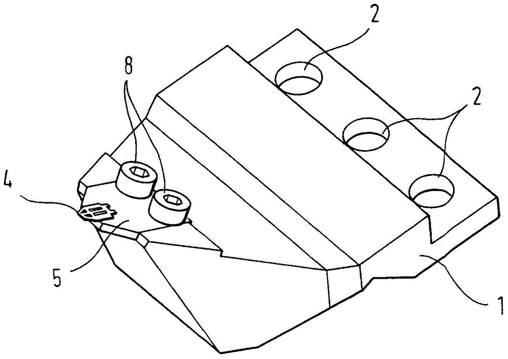
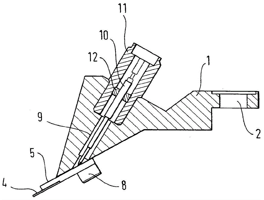
[0026] The measuring head shown in the figures comprises a base body 1 . The base body can be formed, for example, from brass. At the rear end, the basic body 1 has three mounting openings 2 , by means of which the measuring head can be fastened to a structure not shown, for example a robot hand. A recess 3 is formed at the front end of the base for accommodating the measuring unit.

[0027] The measuring unit comprises in this exemplary embodiment coplanar several measuring conductors 4 made of metal, arranged at a defined distance from each other and fixed firmly to the underside of the circuit board 5 . The measuring conductors 4 are electrically insulated from one another. The measuring conductor 4 is fixed in place by soldering. The three measuring conductors 4 are in each case electrically connected via wires (not shown) of the printed circuit board 5 to contact areas 6 on the upper side of the printed circuit board 5 . The circuit board 5 is also formed in its carri...


PUM


Abstract

The present invention relates to a measuring tip comprising a base body, at least two measuring conductors that are connected to the base body, and at least two connecting conductors, a first connecting conductor being electrically conductively connected to one first measuring conductor of the measuring conductors and a second connecting conductor being electrically conductively connected to one second measuring conductor of the measuring conductors, the measuring conductors being fastened on a support element, and the support element being fastened on the base body by means of detachable fastening means so as to be replaceable.

Description

technical field [0001] The invention relates to a measuring tip and a system for variably forming the measuring tip. Background technique [0002] Measuring heads are used, for example, to test the function and electrical properties of circuit boards, for which purpose they are connected to suitable measuring devices via connection contacts. [0003] A measuring head of this general type comprises for this purpose at least one base body which has a supporting function, to which at least two measuring conductors, usually in the form of contact fingers protruding freely into the space, are mounted. The measuring conductors are electrically connected directly or indirectly to connection contacts which are also mounted on the base body. [0004] Such a measuring head is known, for example, from EP 2 409 166 B1. In this case, the measuring conductors are firmly connected to one or both insulations in a coplanar arrangement. This secure connection is usually implemented in prac...

Claims


Application Information

Patent Timeline
Patent Type & Authority Applications(China)
IPC IPC(8): G01R1/067G01R3/00
CPCG01R1/06772G01R3/00G01R1/06711
Inventor R·诺伊豪泽尔
Owner ROSENBERGER HOCHFREQUENZTECHNIK GMBH & CO KG
Why Eureka
Try Eureka