
Verification device of ground fault detection device

A detection device, calibration device technology, applied in the direction of the fault location, measuring device, measuring device casing, etc., can solve problems such as troublesome use, troublesome installation, etc.

Active Publication Date: 2020-09-04
创新电力技术(海南)有限公司
View PDF15 Cites 2 Cited by
  • Summary
  • Abstract
  • Description
  • Claims
  • Application Information

AI Technical Summary

Problems solved by technology

The receiver receives the signal sent by the sensor wirelessly, and displays the measurement data intuitively on the LCD screen. Before the fault point, the current continues to exist, and after the fault point, the current disappears. According to the current change, the fault point is found to realize the function of fault location. However, in actual use, since there is not only a single transmission line on the transmission line, manual operation is required to replace the transmission line to be detected, which is too troublesome to use, and it is not possible to switch to different transmission lines for detection according to needs, and because The transmission line is often located high in the sky, and it is too troublesome to install it manually. In addition, due to the poor installation quality during use, the angle between the device and the transmission line is too large, which seriously affects the verticality. As a result, the device cannot be better installed on the transmission line in the future

Method used


Image

  • Verification device of ground fault detection device
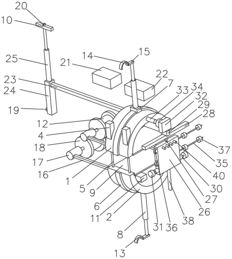
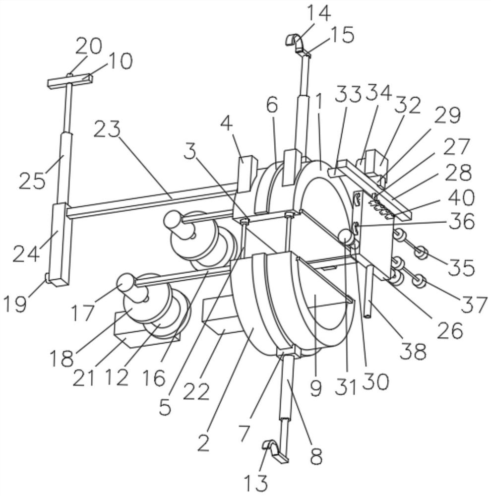
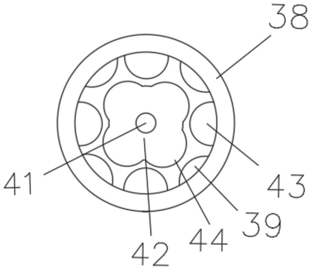
  • Verification device of ground fault detection device
  • Verification device of ground fault detection device

Examples


Embodiment Construction

[0021] In order to better understand the technical content of the present invention, specific embodiments are provided below, and the present invention is further described in conjunction with the accompanying drawings.

[0022] see Figure 1 to Figure 3, a calibration device for a ground fault detection device according to the present invention, comprising a first fixed plate 1 and a second fixed plate 2 with a semi-circular cross-section, the surface of the first fixed plate 1 is provided with several aligned through holes hole 3, the outer periphery of the first fixing plate 1 is provided with a housing 4 aligned with the through hole 3, and the inside of the housing 4 is provided with a first electric telescopic rod 5 fixedly connected thereto. The telescopic end of the first electric telescopic rod 5 is fixedly connected to the end of the second fixed plate 2, and the inner circumference of the first fixed plate 1 and the second fixed plate 2 is provided with a clamping m...


PUM


Abstract

The invention discloses a verification device of a ground fault detection device. The verification device comprises a first fixed plate and a second fixed plate; a plurality of aligned through holes are formed in the surface of the first fixed plate; a shell aligned with the through hole is arranged at the periphery of the first fixed plate; a first electric telescopic rod is arranged in the shell; the telescopic end of the first electric telescopic rod is fixedly connected with the second fixed plate; clamping mechanisms are arranged on the inner circumferences of the first fixed plate and the second fixed plate; a circle of guide rail is arranged at the peripheries of the first fixed plate and the second fixed plate; a plurality of linear motors are arranged on the guide rail; a second electric telescopic rod is arranged on the linear motor; the telescopic end of the second electric telescopic rod is provided with a hanging mechanism; the first fixed plate and the second fixed plateare each provided with a driving mechanism; the first fixed plate is provided with a detection mechanism used for detecting a fault point of a power transmission line. The device can detect multiple power transmission lines and can move towards the power transmission lines in different directions according to needs, and detection of different power transmission lines is achieved.

Description

technical field [0001] The invention relates to transmission line fault detection equipment, in particular to a calibration device for a ground fault detection device. Background technique [0002] The traditional transmission line fault detection equipment outputs a pulsating DC signal through the faulty line of the transmitter, and the current flows through the faulty line and flows into the ground at the fault point. The sensor is connected to the line under test, detects the current on the line, and transmits the collected signal to the receiver by wireless. The receiver receives the signal sent by the sensor wirelessly, and displays the measurement data intuitively on the LCD screen. Before the fault point, the current continues to exist, and after the fault point, the current disappears. According to the current change, the fault point is found to realize the function of fault location. However, in actual use, since there is not only a single transmission line on the ...

Claims


Application Information

Patent Timeline
IPC IPC(8): G01R35/00G01R31/52G01R31/58G01R31/08G01R1/04G01R1/02
CPCG01R35/00G01R31/52G01R31/58G01R31/085G01R1/02G01R1/0408
Inventor 刘青昆
Owner 创新电力技术(海南)有限公司
Learn More