
Intelligent welding equipment for metal furniture stand column

A technology of welding equipment and columns, which is applied in the field of intelligent welding equipment for metal furniture columns, can solve problems affecting work efficiency, troublesome operation, and danger of column welding, and achieve the effect of reducing manual operations and reducing troubles

Pending Publication Date: 2021-12-31
JIANGXI EQUIP INDAL GROUP GREAT INSURANCENT
View PDF7 Cites 0 Cited by
  • Summary
  • Abstract
  • Description
  • Claims
  • Application Information

AI Technical Summary

Problems solved by technology

[0004] Aiming at the deficiencies of the prior art, the present invention provides an intelligent welding equipment for metal furniture uprights that is safe in operation and does not require manual hand-held electric welding to overcome the danger of manual hand-held electric welding on the uprights and the need to rely on hands to press the pillars , the operation is troublesome, and the shortcomings that affect work efficiency

Method used


Image

  • Intelligent welding equipment for metal furniture stand column
  • Intelligent welding equipment for metal furniture stand column
  • Intelligent welding equipment for metal furniture stand column

Examples


Embodiment 1

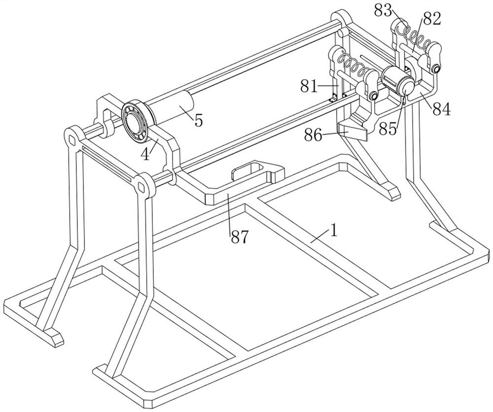
[0037] Such as Figure 1-7The shown intelligent welding equipment for metal furniture columns includes a first support frame 1, a first fixed frame 2, a motor 3, a second fixed frame 4, a rotating rod 5, a second support frame 6, and a first connecting frame 7 , welding mechanism 8, push mechanism 9 and snap-in mechanism 10, the first support frame 1 upper left side sliding type is provided with the first fixed frame 2, and the first fixed frame 2 is provided with the motor 3 that is used to make the post rotate, the first The left side of the upper part of the support frame 1 is slidingly provided with a second fixed frame 4, the second fixed frame 4 is located on the right side of the first fixed frame 2, the second fixed frame 4 is connected with the first fixed frame 2, and the second fixed frame 4 passes through The roller bearing is connected with the rotating rod 5 for being inserted into the column, and the top of the second fixing frame 4 is connected with the second ...

Embodiment 2

[0043] On the basis of Example 1, such as figure 1 , Figure 8 , Figure 9 , Figure 10 , Figure 11 , Figure 12 , Figure 13 , Figure 14 and Figure 15 As shown, a push-out mechanism 11 is also included, and the push-out mechanism 11 includes a second fixed rod 111, a third fixed rod 112, a wedge-shaped rod 113 and a third spring 114, and the top of the second support frame 6 is welded symmetrically with the second fixed rod 111, the right side of the top of the two second fixed rods 111 is provided with a third fixed rod 112, and the two third fixed rods 112 are slidingly provided with wedge-shaped rods 113 for making the base break away from the stop block 105, and the two wedge-shaped A third spring 114 is connected between the rod 113 and the third fixed rod 112 on the same side, and the two wedge-shaped rods 113 are slidably connected with the second fixed rod 111 .

[0044] When processing the column, the electric push rod 92 works to make the motor 3, the rot...


PUM


Abstract

The invention relates to welding equipment, and particularly relates to intelligent welding equipment for a metal furniture stand column. The invention provides the intelligent welding equipment for the metal furniture stand column, and the intelligent welding equipment for the metal furniture stand column is safe to operate and does not need to be manually held by hand for welding. The intelligent welding equipment for the metal furniture stand column comprises a first supporting frame, a first fixing frame, a motor, a second fixing frame, a rotating rod, a second supporting frame and the like, the first fixing frame is arranged on the left side of the upper portion of the first supporting frame in a sliding mode, the motor is arranged on the first fixing frame, the second fixing frame is slidably arranged on the position, located on the right side of the first fixing frame, of the left side of the upper portion of the first supporting frame, the second fixing frame is connected with the first fixing frame and connected with the rotating rod through a roller bearing, and the second supporting frame is arranged on the top of the second fixing frame. An electric push rod works to push the stand column to move rightwards for welding work, manual pushing of the stand column is not needed, and more labor is saved and convenience is achieved.

Description

technical field [0001] The invention relates to welding equipment, in particular to an intelligent welding equipment for metal furniture uprights. Background technique [0002] Metal furniture is iron furniture with metal columns, plates or sticks as the main structure. The columns of metal furniture are usually processed by welding to make them more stable. The traditional welding method is to manually connect the columns of the columns to the base. , and then hand-held electric welding to align the joints for welding. During the welding process, sparks and debris generated by electric welding are easy to splash on the workers, which is not safe enough. In addition, it is necessary to rely on hands to press the pillars during welding to prevent the pillars from shifting. Trouble, affecting work efficiency. [0003] Therefore, it is necessary to design a kind of intelligent welding equipment for metal furniture columns that is safe in operation and effective in work, and do...

Claims


Application Information

Patent Timeline
IPC IPC(8): B23K9/00B23K9/32
CPCB23K9/00B23K9/32B23K9/321
Inventor 熊涛
Owner JIANGXI EQUIP INDAL GROUP GREAT INSURANCENT
Learn More