Gas-liquid two-phase flow corrosion test device for mountain moisture pipeline

A gas-liquid two-phase flow and corrosion test technology, applied in the fields of weather resistance/light resistance/corrosion resistance, measuring devices, instruments, etc., can solve problems such as long gaps, difficulty in obtaining corrosion parameters, and inability to truly restore the flow state of pipelines. The effect of saving test resources and reducing corrosion test cycle

Active Publication Date: 2020-09-04
SOUTHWEST PETROLEUM UNIV
View PDF17 Cites 6 Cited by
  • Summary
  • Abstract
  • Description
  • Claims
  • Application Information

AI Technical Summary

Problems solved by technology

However, the current oil and gas pipeline corrosion experiments are mainly carried out in the reactor, which cannot truly restore the flow state of the pipeline, and is far from the actual wet natural gas flow conditions. parameter

Method used


Image

  • Gas-liquid two-phase flow corrosion test device for mountain moisture pipeline

Examples


specific Embodiment approach

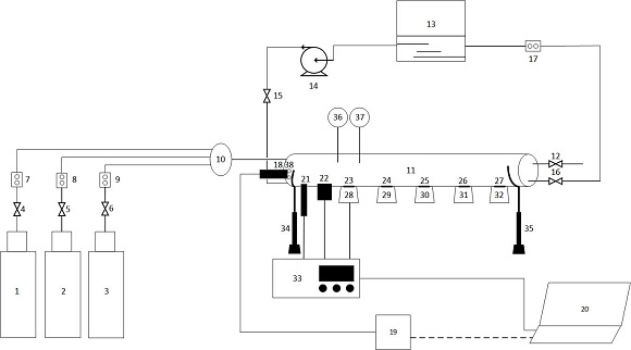
[0021] In the first step, the working electrode (23), the weight loss sample one (24), the weight loss sample two (25), the weight loss sample three (26), and the cross-section observation sample (27) are respectively fixed on the rubber plug one ( 28), rubber plug two (29), rubber plug three (30), rubber plug four (31), rubber plug five (32) are installed on the gas-liquid two-phase flow corrosion test pipe section (11).

[0022] The second step is to adjust the fixed support leg one (34) and the fixed support leg two (35), and set the inclination angle of the gas-liquid two-phase flow corrosion test pipe section (11) and the position of the sample.

[0023] The third step is to open the centrifugal pump (14), the liquid control valve (15), the liquid outlet control valve (16), and the electromagnetic flowmeter (17), so that the test solution enters the gas-liquid two-phase flow corrosion test pipe section (11), and reaches After the ideal liquid level, close the centrifugal ...


PUM


Abstract

The invention discloses a gas-liquid two-phase flow corrosion test device for a mountain moisture pipeline, and relates to the field of wet natural gas pipeline transportation, and aims at the currentsituation that the existing moisture pipeline gas-liquid two-phase flow corrosion test cannot truly restore the working condition of the pipe flow. The invention provides the mountain moisture pipeline gas-liquid two-phase flow corrosion test device, which not only restores the flowing state of the moisture pipeline gas-liquid two-phase flow, but also can simulate the fluctuation change of the mountain pipeline; an electrochemical test, a corrosion weightlessness test and corrosion morphology characterization can be carried out at the same time, the test period is shortened, and thereby the corrosion condition of the mountain moisture pipeline under the gas-liquid two-phase flow working condition is effectively predicted.

Description

technical field [0001] The invention relates to a gas-liquid two-phase flow corrosion test device for a mountain wet gas pipeline, and relates to the field of wet natural gas pipeline transportation. Background technique [0002] There are generally two methods of natural gas transportation: one is to use single-phase pipelines to transport oil and gas separately after the natural gas is processed and separated; the other is to use the wellhead of a gas well with higher pressure to directly transport it to the adjacent gas treatment plant by mixed transportation. However, the former method requires a large investment in the station and needs to be equipped with a large number of staff, and the operating cost is high. Obviously, such a transportation method will lead to a substantial increase in mining costs in harsh environments such as oceans and deserts, and even make some small and medium-sized gas reservoirs impossible to exploit. [0003] At present, whether natural ga...

Claims


Application Information

Patent Timeline
Patent Type & Authority Applications(China)
IPC IPC(8): G01N17/02
CPCG01N17/02
Inventor 覃敏廖柯熹何国玺张世坚赵帅廖德琛邹庆
Owner SOUTHWEST PETROLEUM UNIV
Why Eureka
Try Eureka