Gap calibration method for paired heating rollers of composite material

A composite material and heating roller technology, applied in the field of carbon fiber manufacturing, can solve the problems of large measurement error, influence of operation experience, dangerous operation, etc., to achieve the effect of small measurement error, safe operation, and elimination of interference

Inactive Publication Date: 2020-09-04
WEIHAI GUANGWEI PRECISION MACHINERY
View PDF4 Cites 0 Cited by
  • Summary
  • Abstract
  • Description
  • Claims
  • Application Information

AI Technical Summary

Problems solved by technology

In addition, due to the method of inserting the feeler gauge into the gap, this kind of measurement and calibration requires a lot of experience of the operator, and incorrect measurement methods are likely to cause errors. When the heating roller is heated, the measurement is easy to cause burns due to the small size of the feeler gauge. Danger
Therefore, this traditional measurement method has the disadvantages of large measurement error, dangerous operation, and being affected by operating experience.

Method used


Image

  • Gap calibration method for paired heating rollers of composite material
  • Gap calibration method for paired heating rollers of composite material

Examples


Embodiment 1

[0017] Embodiment one: its concrete steps are:

[0018] Steps to calibrate the gap of the displacement sensor for the first time:

[0019] 1. By using a mechanical feeler gauge for simple calibration, adjust the gap between the two ends of the pair of heating rollers to a value close to 2mm.

[0020] 2. Start the pair of heating rollers to make them rotate at a low speed in the normal working direction.

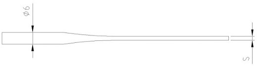
[0021] 3. Put two pieces of pure lead wire with a diameter of 6 mm into the two ends of the heating roller surface 2 (working area) at the same time, let the lead wire rotate with the heating roller (do not drag the lead wire to prevent the lead wire from breaking), and the lead wire is placed between the pair of heating rollers. Plastic deformation occurs under the extrusion of the roller surface 2, and when the lead wire follows and rotates for a certain distance, the heating roller is reversed to make the lead wire back out.

[0022] 4. At this time, the lead wire has be...

Embodiment 2

[0028] In the normal production process, because the heating roller bears a certain working pressure, and the displacement sensor is installed on the bearing seat, it is impossible to know whether the actual gap value is the same as the value displayed by the displacement sensor. At this time, it is necessary to check the gap during use. To measure, the measurement method is as follows:

[0029] 1. Adjust the gap between the paired heating rollers, and the display value of the displacement sensors at both ends is S3.

[0030] 2. Start the heating roller to make it work normally. At this time, the working temperature of the heating roller is F1 degrees Celsius.

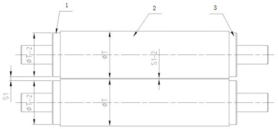
[0031] 3. Cut off two pieces of pure lead wire with a diameter of 6mm and equal length, and put them into the left roller pillow 1 and the right roller pillow 2 at the two ends of the heating roller at the same time (such as figure 2 As shown), let the lead wire rotate together with the heating roller (do not drag th...


PUM


Abstract

The invention relates to a gap calibration method for paired heating rollers of a composite material, and belongs to the field of carbon fiber production. The method includes following steps: using amechanical feeler gauge for calibration, wherein the gap between the two ends of the paired heating rollers is adjusted to a design value; starting the heating rollers in pairs to enable the heating rollers to rotate at a low speed in a normal working direction; placing two pure lead wires in the two ends of the roller surface of the heating roller at the same time, so that the lead wires rotate along with the heating roller and are subjected to plastic deformation under extrusion of the paired heating rollers, and after the lead wires rotate along with the heating roller by a certain distance, reversing the heating roller to release the lead wires; when the lead wire is extruded by the heating roller to deform, measuring the size of the lead wire by using a micrometer, wherein data of multiple positions can be measured, and when the measured data of the multiple positions are consistent, the data is a measured actual value; adjusting the calibration value of the displacement sensor according to the measured actual value, and calibrating the displacement sensor; adjusting the gap between the paired heating rollers according to the measured values displayed by the displacement sensors, so that the measured values displayed by the sensors on two sides are the same.

Description

technical field [0001] The invention belongs to the field of carbon fiber manufacture, and specifically relates to a gap correction method for paired heating rollers of composite materials. Background technique [0002] As we all know, during the use of compound machine / coating machine, it is necessary to set different gap values ​​of pairs of heating rollers according to the finished thickness and processing technology of different prepregs / adhesive films, and the gap between pairs of heating rollers The accuracy of the value determines the performance of the finished prepreg. In existing production equipment, the gap between a pair of heating rollers is measured by a high-precision displacement sensor, but the gap value of the high-precision displacement sensor needs to be checked regularly during its initial use and use. The traditional calibration method is to adjust the heating rollers to the appropriate gap and measure the gap between the pair of heating rollers by in...

Claims


Application Information

Patent Timeline
Patent Type & Authority Applications(China)
IPC IPC(8): G01B21/16G01B5/14
CPCG01B5/14G01B21/042G01B21/16
Inventor 贾钊侯焕斌刘涛吕宝帅张小水
Owner WEIHAI GUANGWEI PRECISION MACHINERY
Why Eureka
Try Eureka