
An automated rack plating pool

A technology of plating tank and transmission belt, applied in the direction of the plating tank, etc., can solve the problems of affecting the plating efficiency of other workpieces, the hooking of the workpiece is not firm, and the workpiece is easily detached from the hanger, etc., so as to ensure the efficiency of electroplating processing, reduce labor consumption, and avoid manual labor. The effect of the salvage process

Active Publication Date: 2021-10-15
太仓市海峰电镀有限公司
View PDF4 Cites 0 Cited by
  • Summary
  • Abstract
  • Description
  • Claims
  • Application Information

AI Technical Summary

Problems solved by technology

[0004] The above-mentioned existing technical solutions have the following defects: since the hanging of the workpiece on the hanger is a manual operation, it is easy to appear that the hooking of the workpiece is not firm
When the hanger enters the inside of the rack plating pool, the solution in the rack plating pool gives the workpiece a certain buoyancy, and the workpiece is easy to break away from the hanger and fall to the bottom of the rack plating pool
Since the workers will not check the workpieces on the hanger at any time during the processing, it is often found that the lack of workpieces on the hanger is in the receiving process. At this time, the workers need to check the hanging plating pool one by one to find out the dropped workpieces. This process wastes manpower, and because the depth of the rack plating pool is deep, the workpiece is not easy to take out, which affects the plating efficiency of other workpieces

Method used


Image

  • An automated rack plating pool
  • An automated rack plating pool
  • An automated rack plating pool

Examples


Embodiment Construction

[0039] The present invention will be further described in detail below with reference to the accompanying drawings.

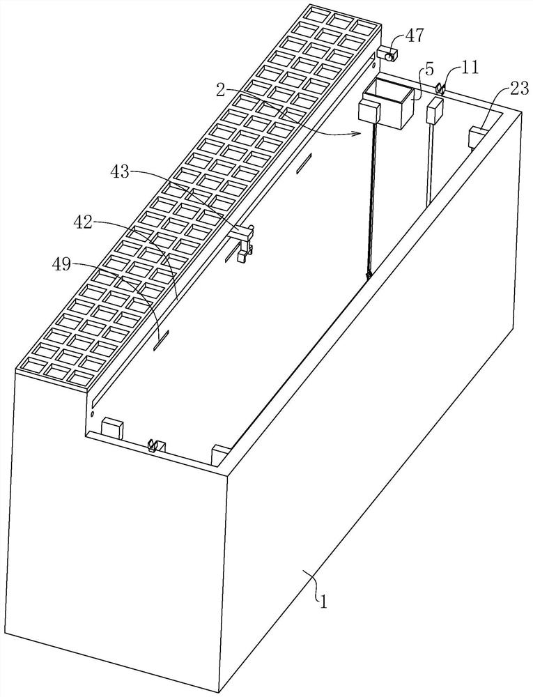
[0040] refer to figure 2 , is an automatic rack plating tank disclosed in the present invention, comprising a rack plating tank body 1, the rack plating tank body 1 is in the shape of a rectangular box as a whole, and the length of the cross section of the rack plating tank body 1 is 4 times the width of the cross section. The height of the plating tank body 1 is twice the cross-sectional width of the rack plating tank body 1 . The upper end of the rack plating tank body 1 is open and the inside is hollow, and the rack plating tank main body 1 is used for containing the solution.

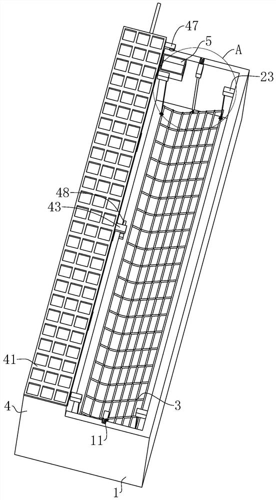
[0041] refer to image 3 , There is a salvage net 3 in the main body 1 of the hanging plating tank, and the salvage net 3 is rectangular as a whole. The vertical inner side walls of the rack plating tank body 1 are all connected with protective covers 23, and the protective cover...


PUM


Abstract

The invention relates to an automatic rack plating pool, which includes a rack plating pool body, the upper surfaces of both sides of the rack plating pool body are provided with supports for receiving hangers, and two vertical racks adjacent to the rack plating pool body and the support A plurality of winding assemblies are connected to the inner wall, and the winding assembly includes a winding elastic member connected to the inner wall of the hanging plating tank body. A connecting rope is connected to the winding elastic member. There is a salvage net, and the corners of the salvage net are respectively connected with one of the connecting ropes. After the hanger enters the main body of the rack plating pool, it drives the salvage net to move downward. When a workpiece leaves the hanger, the workpiece falls into the salvage net; Pulling to move to the upper end of the rack plating tank body, it is convenient for workers to find workpieces in the rack plating tank body. The invention has the effects of high degree of automation, low manual labor, less manpower consumption, high electroplating processing efficiency and high environmental quality of production workshops.

Description

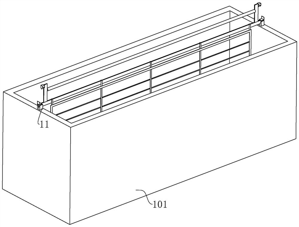
technical field [0001] The invention relates to the technical field of rack plating processing, in particular to an automated rack plating tank. Background technique [0002] Rack plating, also known as hanging plating, is one of the most common plating methods. The usual rack plating process is to manually hook the workpiece on the hanger, and the hanger follows the transmission device to move to the rack plating tank. The rack plating tank is usually a plurality of continuous and relatively independent tanks. Depending on the plating process, Hold different solutions in different rack plating tanks. Then the workpieces carried by the rack are immersed in each rack plating tank in turn to complete the electroplating process. [0003] Existing rack plating tank structures such as figure 1 As shown in the figure, it includes a rectangular pool body 101, the upper surfaces of the two sides of the rectangular pool body 101 are connected with supports 11 for receiving hangers...

Claims


Application Information

Patent Timeline
Patent Type & Authority Patents(China)
IPC IPC(8): C25D17/02
CPCC25D17/02
Inventor 王海峰王培明郭晓阳高建军
Owner 太仓市海峰电镀有限公司
Learn More