Device for hydrogen production through electrolysis of water and with strong hydrogen desorption performance
A hydrogen production device and water electrolysis technology, applied in the electrolysis process, electrolysis components, electrodes and other directions, can solve the problems of slow hydrogen desorption and limited efficiency, and achieve the effects of simple structure, improved efficiency and convenient use.
- Summary
- Abstract
- Description
- Claims
- Application Information
AI Technical Summary
Problems solved by technology
Method used
Image
Examples
Embodiment 1
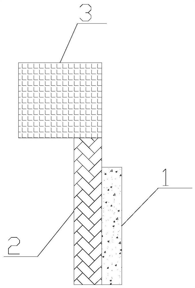
[0018] The invention provides a strong hydrogen desorption electrolysis water hydrogen production device, which comprises an electrolytic cell, an anode, a cathode and a diaphragm. The anode, cathode, and diaphragm are placed in the electrolytic cell. A separator is placed between the anode and cathode. The electrode material of the anode is platinum, graphite, graphene or titanium dioxide. The cathode is the carbon nanotube layer 1 . like figure 1 As shown, the carbon nanotube layer 1 is fixed on the cantilever beam 2, and the cantilever beam 2 is a semiconductor material or diamond. The cantilever beam 2 is fixed on the base 3, and the base 3 is connected with a vibration source, and the vibration source drives the base 3 to vibrate.
[0019] When in use, in the electrolyte, the anode generates electrons after absorbing light, and the electrons flow to the cathode through the external circuit, and the hydrogen ions in the water receive electrons at the cathode to generat...
Embodiment 2
[0023] On the basis of Example 1, a conductive hoop layer is provided outside the carbon nanotube layer 1 . The conductive mesh hoop layer is activated carbon fiber. In this way, on the one hand, the conductive mesh hoop layer prevents the carbon nanotube layer 1 from falling off; on the other hand, the conductive mesh hoop layer is activated carbon fiber, and the activated carbon fiber can also be used as a cathode to generate hydrogen on the activated carbon fiber.
Embodiment 3
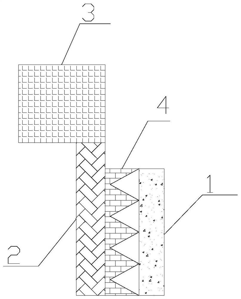
[0025] On the basis of Example 1, such as figure 2 As shown, it also includes a tapered layer 4 , the tapered layer 4 is fixed on the cantilever beam 2 , and the carbon nanotube layer 1 is fixed on the tapered layer 4 . The tapered layer 4 comprises pointed cones. The material of the tapered layer 4 is nickel. The tapered layer 4 has more surface area relative to the planar structure. During application, the volume of hydrogen gas bubbles formed on the surface of the tapered layer 4 is smaller, and the hydrogen gas bubbles are easier to detach from the carbon nanotube layer 1; in addition, the present invention fixes the tapered layer 4 and the carbon nanotube layer 1 on the cantilever beam 2 Above all, the vibration of the cantilever beam 2 makes it easier for the hydrogen bubbles in this embodiment to detach from the carbon nanotubes, improving the hydrogen desorption capacity, thereby improving the hydrogen production efficiency of the device.
[0026] Furthermore, the ...
PUM
 Abstract
Description
Claims
Application Information
 - R&D Engineer
- R&D Manager
- IP Professional
- Industry Leading Data Capabilities
- Powerful AI technology
- Patent DNA Extraction
Browse by: Latest US Patents, China's latest patents, Technical Efficacy Thesaurus, Application Domain, Technology Topic, Popular Technical Reports.
© 2024 PatSnap. All rights reserved.Legal|Privacy policy|Modern Slavery Act Transparency Statement|Sitemap|About US| Contact US: help@patsnap.com


