
Automobile composite pedestrian protection beam

A composite material and pedestrian protection technology, applied in pedestrian/occupant safety arrangement, bumper, vehicle parts, etc., can solve the problems of small living space for pedestrians, insufficient material strength, large local deformation, etc., and achieve low preparation cost and advanced performance , the effect of increasing strength

Pending Publication Date: 2020-09-04
JIANGSU UNIV OF TECH
View PDF13 Cites 3 Cited by
  • Summary
  • Abstract
  • Description
  • Claims
  • Application Information

AI Technical Summary

Problems solved by technology

In terms of materials, CN201520983412.1 uses foamed polyethylene, CN201820293854.7 uses a kind of integrated flexible material, and CN201520756968.7 uses PP-LGF plastics. Although lightweight materials are used, the disadvantage is that The strength of the material is not enough, it can absorb the impact energy and automatically return to its original shape in a minor accident, but it cannot withstand a large impact in a serious accident, and the impact force cannot be well distributed to the entire body, which will cause excessive local deformation and damage to pedestrians. small living space
Structurally, CN201820293854.7 and CN201520756968.7 disclose a row of parallel ribs distributed along the length of the body on the protective beam, CN201520356268.9 is designed with discontinuous and unevenly distributed ribs, and CN201520444316.X is designed with a cross-sectional shape of Arc-shaped ribs, the disadvantage of this type of rib structure is that these designs are only beneficial to improve the local strength of the protective beam, but the protective beam is a curved part, and the overall deformation will occur when it is impacted

Method used


Image

  • Automobile composite pedestrian protection beam
  • Automobile composite pedestrian protection beam
  • Automobile composite pedestrian protection beam

Examples


Embodiment Construction

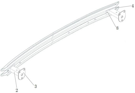
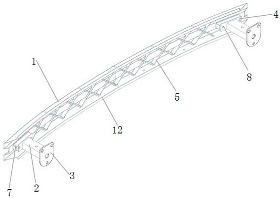
[0028] Attached below Figure 1-8 The preferred embodiments of the present invention are described in detail, so that the advantages and features of the present invention can be more easily understood by those skilled in the art, so as to define the protection scope of the present invention more clearly.

[0029] In order to ensure the structural strength of the automobile pedestrian protection beam while achieving light weight, and improve the safety protection factor during use, this embodiment discloses an automobile composite material pedestrian protection beam structure, including a protection beam body 1 and an energy-absorbing box 2 , negative sheet 3 and metal aluminum sheet 4, the protective beam body 1 is integrally molded, the main body shape of the protective beam body 1 is similar to the existing protective beam so as to be suitable for the installation position and installation requirements on the original vehicle type, and the protective beam body One end of the...


PUM


Abstract

The invention discloses an automobile composite pedestrian protection beam. The automobile composite pedestrian protection beam comprises a protection beam body formed through integrated compression molding, an energy absorption box used for absorbing impact force borne by the protection beam, and a rectangular aluminum sheet connected between the energy absorption box and the protection beam body, wherein the protection beam body is made of a glass fiber composite material, the surface of the protection beam body is reinforced by carbon fibers or aramid fibers to improve the strength of the protection beam, and the protection beam body and carbon fibers or aramid fibers are connected in an adhesive mode; the section of the protection beam is designed to be M-shaped, and continuous geometric reinforcing ribs are arranged on the inner side of the protection beam; and in order to be effectively connected with the energy absorption box, the two ends of the protection beam are each provided with a sunken cuboid groove, and the bottom surfaces of the grooves are connected with the energy absorption box through the aluminum sheets. The pedestrian protection beam is manufactured by adopting a compression molding process, the process is simple, and large-batch manufacturing can be realized; and the composite material is adopted for design, the dead weight is effectively reduced while the strength of the protection beam is guaranteed, and the lightweight design is achieved.

Description

technical field [0001] The invention relates to the field of lightweight design of automobile structural parts, in particular to an automobile composite material pedestrian protection beam. Background technique [0002] With the rapid growth of car ownership, traffic accidents occur frequently. As a device to protect pedestrians in the car structure, the pedestrian protection beam can play a role in buffering and protecting pedestrians when there is a low-speed collision between the car and pedestrians, reducing the impact on pedestrians. Injuries caused by pedestrians, while also reducing the risk of pedestrians being involved in the vehicle. [0003] Nowadays, due to the consideration of energy and environmental protection issues, it has become a general trend for the design of automobile pedestrian protection beams to be lightweight. [0004] CN201520983412.1, CN201820293854.7, CN201520444316.X, CN201520356268.9, CN201520756968.7, etc. have disclosed the designs of vario...

Claims


Application Information

Patent Timeline
IPC IPC(8): B60R21/34B60R19/34B60R19/03
CPCB60R21/34B60R19/34B60R19/03B60R2021/343
Inventor 曹清林朱佳辉高立新周甘华邱睿朱浩朱佳文
Owner JIANGSU UNIV OF TECH
Learn More