
A method for mapping pressure footprint image by optical footprint image

A footprint and image technology, applied in the field of optical footprint image mapping pressure footprint image, can solve the problems of high machine cost and impossibility, and achieve the effect of omitting instruments and equipment

Active Publication Date: 2020-09-01
ANHUI UNIVERSITY
View PDF3 Cites 0 Cited by
  • Summary
  • Abstract
  • Description
  • Claims
  • Application Information

AI Technical Summary

Problems solved by technology

[0003] At present, the pressure footprint image is obtained by the person being collected standing or walking on the pressure plate, which requires manual operation, high machine cost, and regular maintenance is required to prevent the damage of the pressure collector from affecting the normal collection of the pressure footprint
And for the crime scene, it is impossible to obtain the pressure footprint image of the suspect in this way

Method used


Image

  • A method for mapping pressure footprint image by optical footprint image
  • A method for mapping pressure footprint image by optical footprint image
  • A method for mapping pressure footprint image by optical footprint image

Examples


Embodiment Construction

[0029] The following will clearly and completely describe the technical solutions in the embodiments of the present invention with reference to the accompanying drawings in the embodiments of the present invention. Obviously, the described embodiments are only some, not all, embodiments of the present invention. Based on the embodiments of the present invention, all other embodiments obtained by persons of ordinary skill in the art without making creative efforts belong to the protection scope of the present invention.

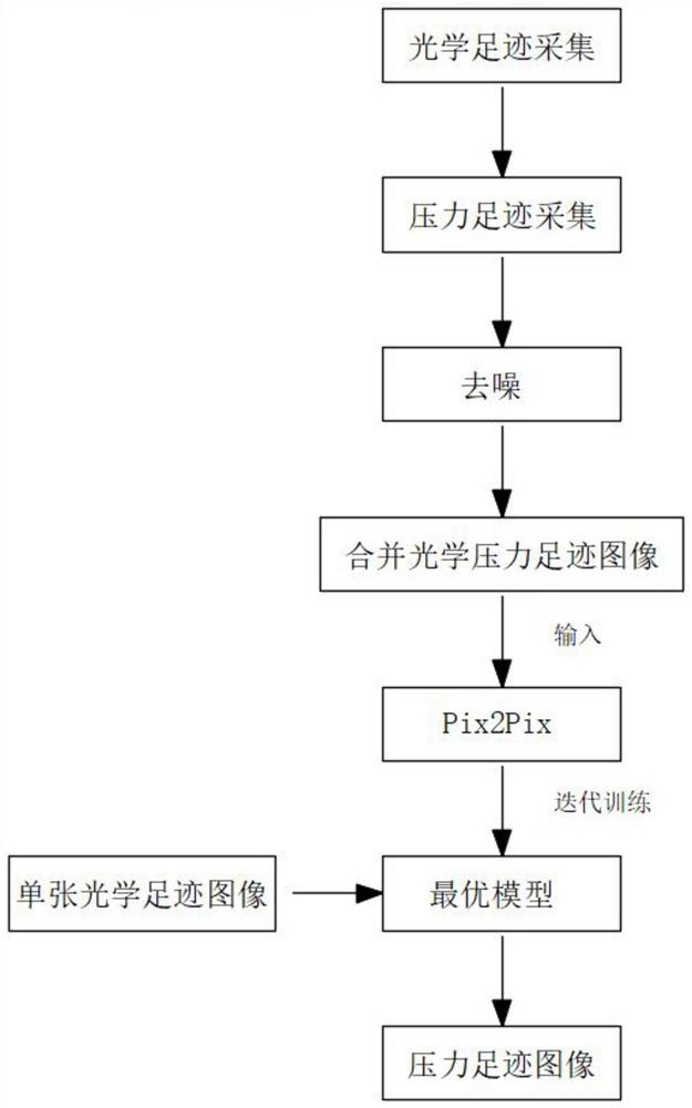
[0030] see Figure 1-7 , the present invention provides a technical solution: a method for mapping an optical footprint image to a pressure footprint image, comprising the following steps:

[0031] S1: collection of optical footprint images;

[0032] S2: Acquisition of pressure footprint images;

[0033] S3: filter and denoise the pressure footprint image collected in S2;

[0034] S4: Merge the optical footprint image in S1 and the denoised pressure footpri...


PUM


Abstract

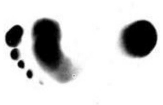
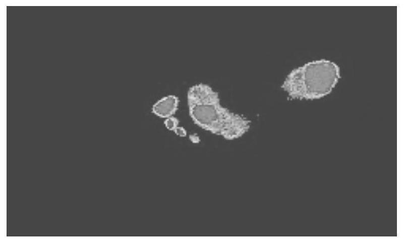
The invention discloses a method for mapping a pressure footprint image by an optical footprint image. The method comprises the following steps: S1, acquiring the optical footprint image; S2, acquiring a pressure footprint image; S3, filtering and denoising the pressure footprint image acquired in the step S2; S4, combining the optical footprint image in S1 and the denoised pressure footprint image in S3 into one image as a training image; S5, importing the plurality of training images into a computer, and utilizing a Pix2Pix algorithm to obtain an optimal model through the continuous game ofa generator and a discriminator of the Pix2Pix algorithm; S6, collecting a single optical footprint image, importing the single optical footprint image into the optimal model obtained in S5, and mapping a pressure footprint image. The optical footprint image can be mapped into the pressure footprint image, and therefore the reliable pressure footprint image of the target individual is provided forpublic security and scientific research staff and used for analyzing morphological characteristics of the pressure footprint image.

Description

technical field [0001] The invention relates to the technical field of image processing and biological feature recognition, in particular to a method for mapping a pressure footprint image from an optical footprint image. Background technique [0002] Pix2Pix can achieve direct conversion of matching images in the two fields, and the obtained results are relatively clear; the main idea of ​​the U-net network is derived from FCN, which uses a fully convolutional network to classify images pixel by pixel, which can be achieved in the field of image segmentation. Good effect, because the network structure is similar to U-shaped, so it is named after this, its composition is composed of the convolution compression layer on the left end, and the transposed convolution amplification layer on the right end; PatchGAN discriminator is a kind of discriminant model, Intuitively, it is completely composed of convolutional layers, and the final output is an n*n matrix, and finally the me...

Claims


Application Information

Patent Timeline
Patent Type & Authority Applications(China)
IPC IPC(8): G06T5/50G06T5/00G06T7/10G06N3/04
CPCG06T5/50G06T7/10G06T2207/10004G06T2207/20081G06T2207/20084G06N3/045G06T5/70Y02T10/40
Inventor 高梓健王年张艳唐俊朱明鲍文霞
Owner ANHUI UNIVERSITY
Learn More