
Laser heating roller type micro-imprinting device

A laser heating, roll-forming technology, applied in decorative arts, embossed decorative parts, etc., can solve the problems of low quality of imprinted products, uneven flow filling, high resistance to material deformation, etc., to improve forming stability and forming. Accuracy, good thermal action controllability, good guiding performance

Active Publication Date: 2020-09-01
NANJING VOCATIONAL UNIV OF IND TECH
View PDF7 Cites 2 Cited by
  • Summary
  • Abstract
  • Description
  • Claims
  • Application Information

AI Technical Summary

Problems solved by technology

[0006] However, the above method adopts cold roll embossing, which easily leads to high deformation resistance of the material, and the material flows and deforms at a micro scale. Due to the existence of the size effect, the influence of the material type, grain size and orientation will cause the material to flow fully during the micro deformation process. The shape is uneven, the process parameters are unstable, and the quality of the imprinted product is not high

Method used


Image

  • Laser heating roller type micro-imprinting device
  • Laser heating roller type micro-imprinting device
  • Laser heating roller type micro-imprinting device

Examples


Embodiment 1

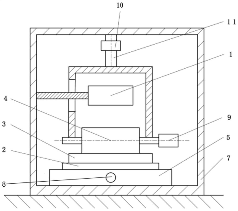
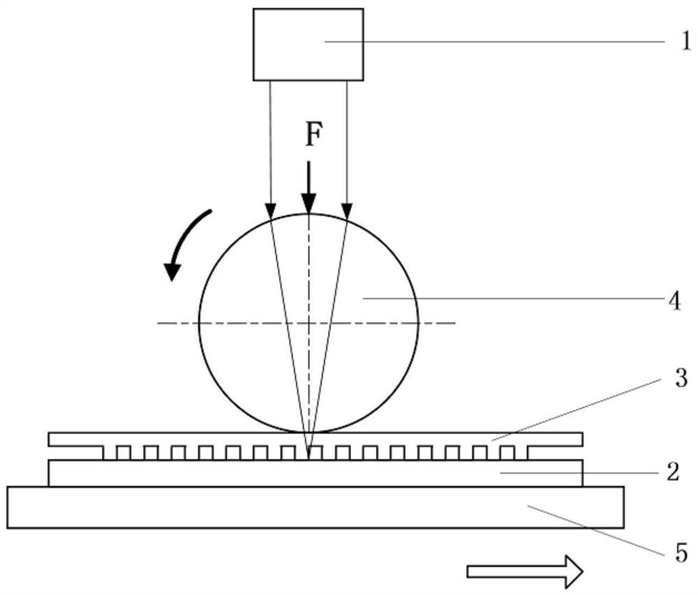
[0041] Such as figure 2 As shown, the transparent mold 3 and the transparent roller 4 are set separately. The transparent mold 3 is a flat mold placed on the upper surface of the material 2. The transparent mold 3 is transported along the support along with the material 2 synchronously. The direction in which the mechanism runs moves, and the translucent roller 4 rolls relative to the upper surface of the translucent mold 3 .

[0042] The supporting transport mechanism is a linear motion platform 5, and the linear motion platform 5 is driven by the first driving mechanism 8 to perform linear reciprocating motion. The linear motion platform 5 can adopt sliding guide rails, rolling guide rails, hydraulic guide rails, air-floating guide rails or magnetic levitation guide rails. Any one of them, the first driving mechanism 8 is a servo motor or a linear motor.

[0043] In this embodiment, when material 2 is embossed with a laser heating roller, the steps are as follows:

[0044] ...

Embodiment 2

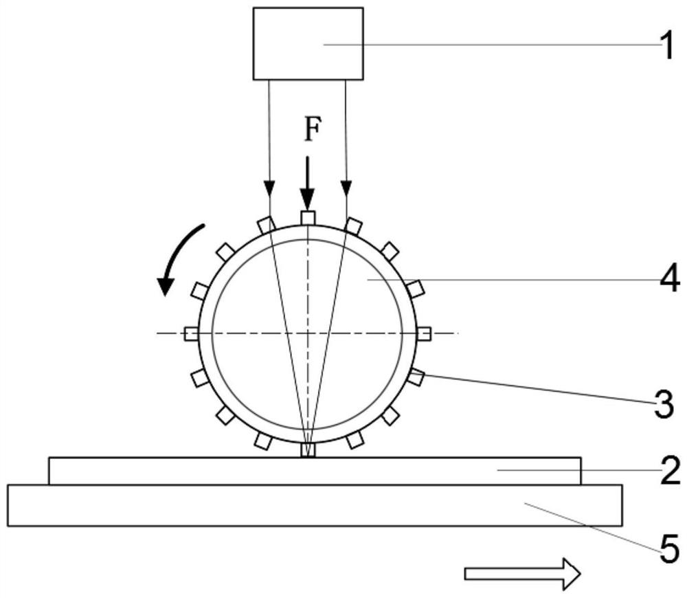
[0050] Such as image 3 As shown, based on Example 1, the light-transmitting mold 3 is replaced, specifically: the light-transmitting mold 3 surrounds the outer roll wall of the light-transmitting roller 4, and is integrally formed with the light-transmitting roller 4. During the rotation of the light roller 4 , the light-transmitting mold 3 on it acts on the surface of the material 2 . Roll embossing has the following steps:

[0051] The first step is to adjust the height of the transparent roller 4, and place the material 2 to be rolled on the linear motion platform 5;

[0052] The second step is to adjust the rolling gap regulator 11, so that the light-transmitting roller 4 moves vertically downward, and the microstructure on the surface of the light-transmitting mold 3 on the outer ring of the light-transmitting roller 4 is pressed into the surface layer of the material 2 to the required rolling depth;

[0053] The third step is to turn on the laser 1, adjust the focal l...

Embodiment 3

[0055] Such as Figure 4 , based on Embodiment 1, the linear motion platform 5 is replaced by a rotating roller 6, that is, the supporting transport mechanism is a rotating roller 6, and the rotating roller 6 is driven to rotate by a first drive mechanism 8, and the rollers of the rotating roller 6 and the light-transmitting roller 4 Shafts are parallel to each other, and the rotating roller 6 is mounted on the frame 7 through a bearing, the bearing is any one of a hydraulic bearing, an air bearing or a magnetic bearing, and the first driving mechanism 8 is a servo motor or a brushless motor , hydraulic motor or air motor in any one. Roll embossing has the following steps:

[0056] The first step is to adjust the height of the light-transmitting roller 4, place the material 2 to be rolled on the rotating roller 6, and place the light-transmitting mold 3 on the top of the material 2, so that the side of the light-transmitting mold 3 with microstructure features is in line with...


PUM


Abstract

The invention discloses a laser heating roller type micro-imprinting device. The laser heating roller type micro-imprinting device comprises a frame, a supporting and conveying mechanism, a laser device, a transparent mold, a transparent roller and a rolling gap adjusting mechanism; the transparent roller is rotatably arranged at the lower end of the rolling gap adjusting mechanism; the laser device is arranged above the transparent roller; a central rotating shaft of the transparent roller and the conveying direction of the supporting and conveying mechanism are perpendicular to each other; the transparent roller acts on the surface of the transparent mold; a rolling gap is formed between the transparent mold and the supporting and conveying mechanism; materials are placed at the rollinggap; and laser beams emitted by the laser device sequentially pass through the transparent roller and the transparent mold to act on the materials. According to the laser heating roller type micro-imprinting device, impressing force is reduced through the near-linear contact between the transparent roller, the transparent mold and the materials, the molding stability and the molding precision of the materials are improved by adopting a laser non-contact mode to heat micro-forming areas on the surfaces of the materials; and a traditional rolling process is combined with a plane impressing process, and the imprinting efficiency is improved.

Description

technical field [0001] The invention relates to the technical field of micro-manufacturing equipment, in particular to a laser heating roller type micro-imprinting device. Background technique [0002] Functional surface fine structure refers to the characteristic size range of the product surface fine structure is 0.01 ~ 1mm, which is between the micro scale and the macro scale (called meso scale). These surface fine structures can enhance product functions and improve products performance, and optimize product economy and eco-environmental protection, especially large-area functional surface microstructures such as micro-channels, micro-ribs, micro-pits, etc., such as increasing the reaction area, reducing friction and drag, and improving energy utilization There are significant advantages in terms of rate and so on. [0003] At present, products with large-area functional surface fine feature structures are increasingly used in new energy devices, optical devices, energy...

Claims


Application Information

Patent Timeline
Patent Type & Authority Applications(China)
IPC IPC(8): B44B5/00B44B5/02
CPCB44B5/0052B44B5/02B44B5/026
Inventor 高照阳缪辉周滔温玉锋李红刚王康吴志威
Owner NANJING VOCATIONAL UNIV OF IND TECH
Learn More