Setting machine tail gas flue gas particulate matter concentration detection system and method

A particle concentration and detection system technology, which is applied in the field of particle concentration detection system in the tail gas of the setting machine, can solve the problems of zirconia loss, failure to respond to the degree of fabric drying in time, and increase the cost of real-time online detection, etc., to achieve Good real-time performance and avoid over-baking effect

Pending Publication Date: 2020-08-28
ZHEJIANG SCI-TECH UNIV +1
View PDF0 Cites 0 Cited by
  • Summary
  • Abstract
  • Description
  • Claims
  • Application Information

AI Technical Summary

Problems solved by technology

At present, most of them judge the drying degree of the fabric by the setting machine by detecting the concentration of water vapor in the oven of the setting machine, but this method cannot reflect the drying degree of the fabric in time, and because the detection process has a certain delay , there are great limitations in the use of
[0003] Furthermore, this detection method usually adopts the oxygen atom method when detecting humidity, and uses a zirconium dioxide sensor. When detecting by oxygen atoms, since there is oxygen in the air, there is a large gap in the detection of water vapor concentration by zirconium dioxide. At the same time, the zirconia sensor detects the water vapor concentration according to the chemical reaction, so the zirconia will be lost during the working process. Therefore, in industrial practice, the detection sensor probe needs to be replaced every three years, which increases the The cost of real-time online detection, and the detection accuracy is low

Method used


Image

  • Setting machine tail gas flue gas particulate matter concentration detection system and method
  • Setting machine tail gas flue gas particulate matter concentration detection system and method
  • Setting machine tail gas flue gas particulate matter concentration detection system and method

Examples


Embodiment

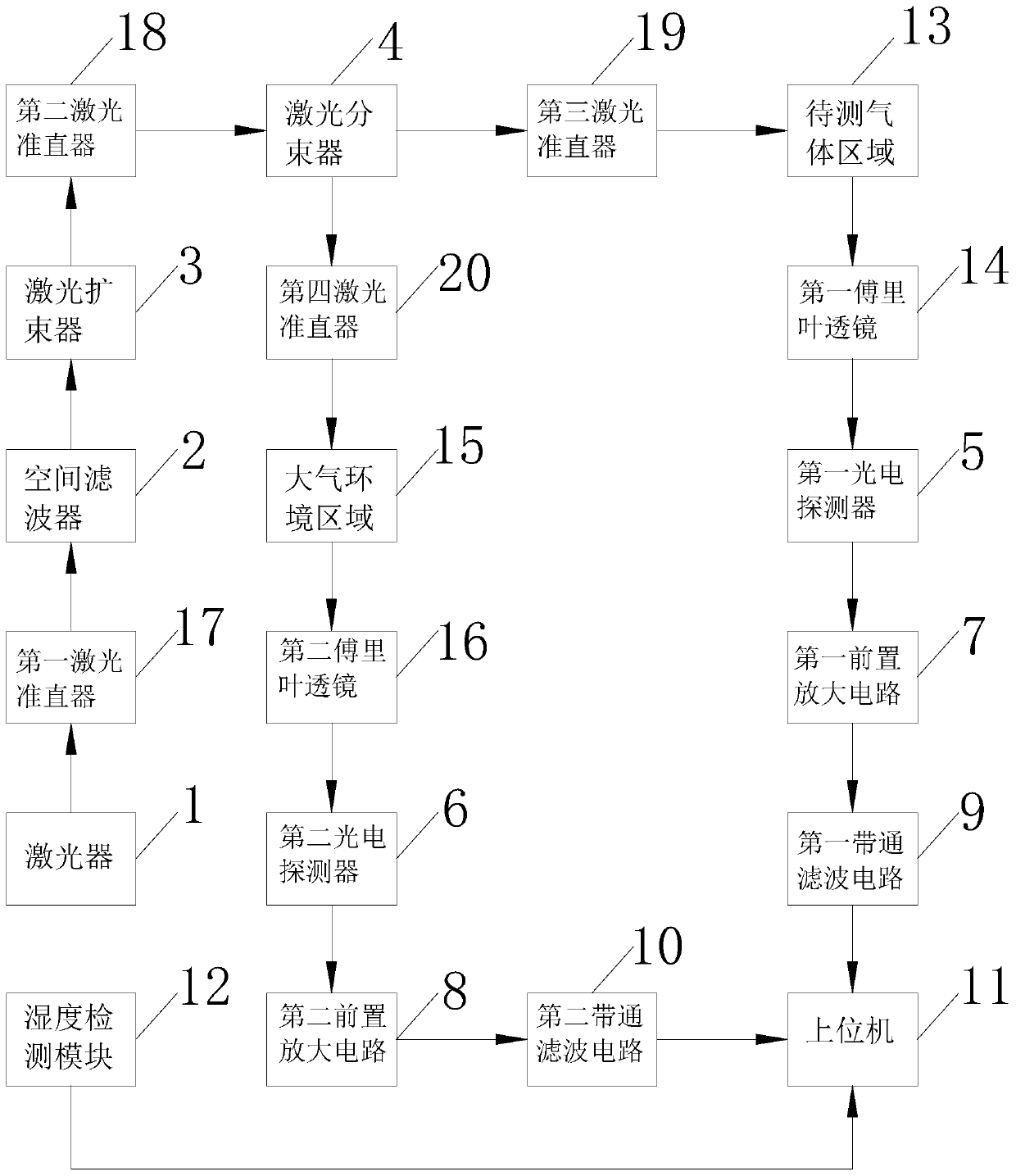
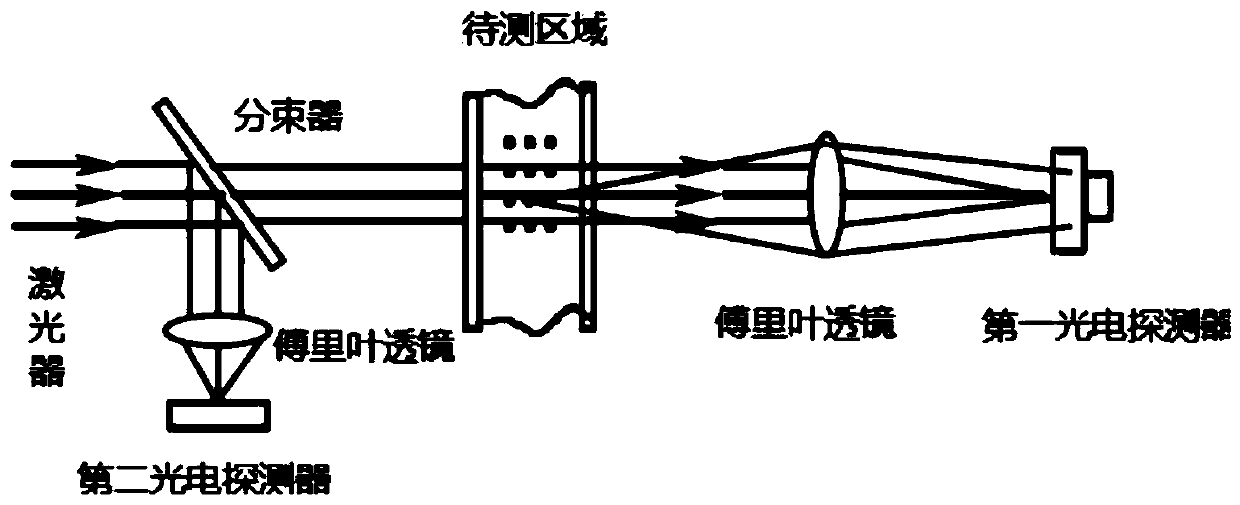
[0031] A detection system for the concentration of smoke particles in the tail gas of a setting machine, please refer to the attached figure 1 - attached figure 2 The detection system includes a laser 1, a spatial filter 2, a laser beam expander 3, a laser beam splitter 4, a first photodetector 5, a second photodetector 6, a first preamplifier circuit 7, a second Preamplifier circuit 8, first band-pass filter circuit 9, second band-pass filter circuit 10, host computer 11, and humidity detection module 12; laser light emitted by laser 1 is filtered by spatial filter 2 and then injected into laser expansion The beam splitter 3 is injected into the laser beam splitter 3, and the laser beam splitter 3 splits the injected laser beam into the first laser beam and the second laser beam at 1:1; the first laser beam passes through the gas to be measured vertically After the area 13 is injected into the first photodetector 5 through the first Fourier lens 14, the first photodetector ...


PUM


Abstract

The invention provides a setting machine tail gas flue gas particulate matter concentration detection system and method. The detection and system comprises a laser, a spatial filter, a laser beam expander, a laser beam splitter, a first photoelectric detector, a second photoelectric detector, a first pre-amplification circuit, a second pre-amplification circuit, a first band-pass filter circuit, asecond band-pass filter circuit, an upper computer and a humidity detection module. The detection method is based on a laser extinction method theory. Calculating the front-back illumination intensity value ratio after the laser passes through the tail gas area of the setting machine through an upper computer; the setting machine tail gas humidity detection method has the advantages that the drying degree of the fabric can be reflected in real time through the particle concentration, the over-drying phenomenon is effectively avoided, and compared with the traditional humidity detection method, the setting machine tail gas humidity detection method has better real-time performance, rapidity and accuracy.

Description

technical field [0001] The invention relates to the field of particle concentration detection and textile setting machine parameter detection, in particular to a system and method for detecting particle concentration in tail gas of a setting machine. Background technique [0002] The concentration of particulate matter in the tail gas of the textile setting machine is an important indicator for controlling whether the oven of the setting machine causes over-drying of the textiles, and it is of great significance to the energy saving of the textile industry. At present, most of them judge the drying degree of the fabric by the setting machine by detecting the concentration of water vapor in the oven of the setting machine, but this method cannot reflect the drying degree of the fabric in time, and because the detection process has a certain delay , there are great limitations in use. [0003] Furthermore, this detection method usually adopts the oxygen atom method when detec...

Claims


Application Information

Patent Timeline
Patent Type & Authority Applications(China)
IPC IPC(8): G01N15/06G01N15/02
CPCG01N15/0205G01N15/06G01N2015/0693
Inventor 张建新申雪韵丁伯军钱淼
Owner ZHEJIANG SCI-TECH UNIV
Why Eureka
Try Eureka