
Double-sided flat panel louver canopy

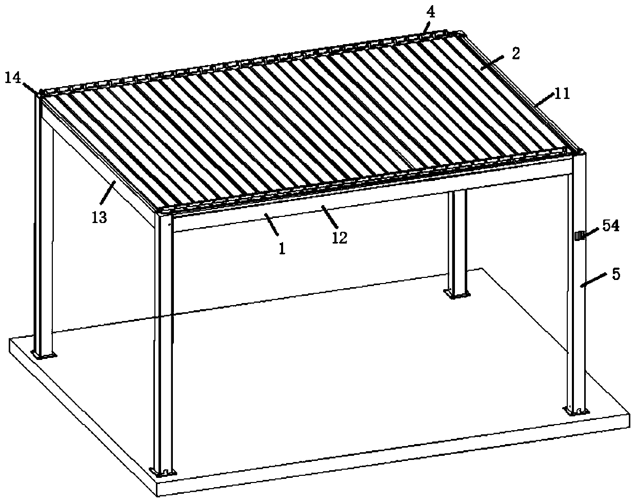
A kind of louvered canopy and flat plate technology, applied in the direction of roof, roof covering, roof drainage, etc., can solve the problems of simple structural materials, the overall design of the louver canopy is not beautiful and harmonious, and the structural design is unreasonable.

Inactive Publication Date: 2020-08-28
广东格绿朗节能科技有限公司
View PDF6 Cites 1 Cited by
  • Summary
  • Abstract
  • Description
  • Claims
  • Application Information

AI Technical Summary

Problems solved by technology

[0003] Traditional louver awnings generally have the problems of poor structural materials and unreasonable structural design, and cannot cope with bad weather. They are prone to damage when encountering strong wind and heavy rain, and have the problem of low service life; moreover, the traditional louver awning is easy to operate It is very troublesome and affects the actual use effect of users; in addition, the overall design of the traditional louver awning is not beautiful and harmonious enough, which affects the user's perception

Method used


Image

  • Double-sided flat panel louver canopy
  • Double-sided flat panel louver canopy
  • Double-sided flat panel louver canopy

Examples


Embodiment 1

[0116] Figure 21 It is a schematic diagram of the explosion of the manual handpiece in the embodiment of the present invention, Figure 22 It is a schematic diagram of the connection of the manual handpiece in the embodiment of the present invention.

[0117] In the first embodiment, the driving device is a manual handpiece 31 arranged in the right beam 14 .

[0118] Specifically, the middle part of the driving end plate 212 is provided with a driving hole 2121, and the output end of the manual machine head 31 is provided with a machine head transmission shaft 32 adapted to the driving hole 2121, and the machine head transmission shaft 32 is connected with the drive hole 2121, the head drive shaft 32 is driven by the manual head 31 to rotate, and based on the connection between the head drive shaft 32 and the drive hole 2121, the active double-sided The rotation of flat shutter 21.

[0119] It should be noted that the manual handpiece 31 is driven based on a worm gear, the...

Embodiment 2

[0124] Figure 23 It is a schematic diagram of the connection between the electric drive device and the active double-sided flat louvers in the embodiment of the present invention, Figure 24 It is a schematic diagram of the position of the electric drive device in the embodiment of the present invention, Figure 25 It is a schematic diagram of the three-dimensional structure of the louver drive knife in the embodiment of the present invention.

[0125] In the second embodiment, the driving device is an electric driving device 4, and the electric driving device 4 is fixed on the inner side of the right crossbeam 14, and the electric driving device 4 is located in the second water tank close to the front crossbeam 11 at one end.

[0126] Specifically, the driving end of the electric driving device 4 is connected to the driving end plate 212 through the louver transmission knife 35, wherein one end of the louver transmission knife 35 is connected to the driving end of the elec...


PUM


Abstract

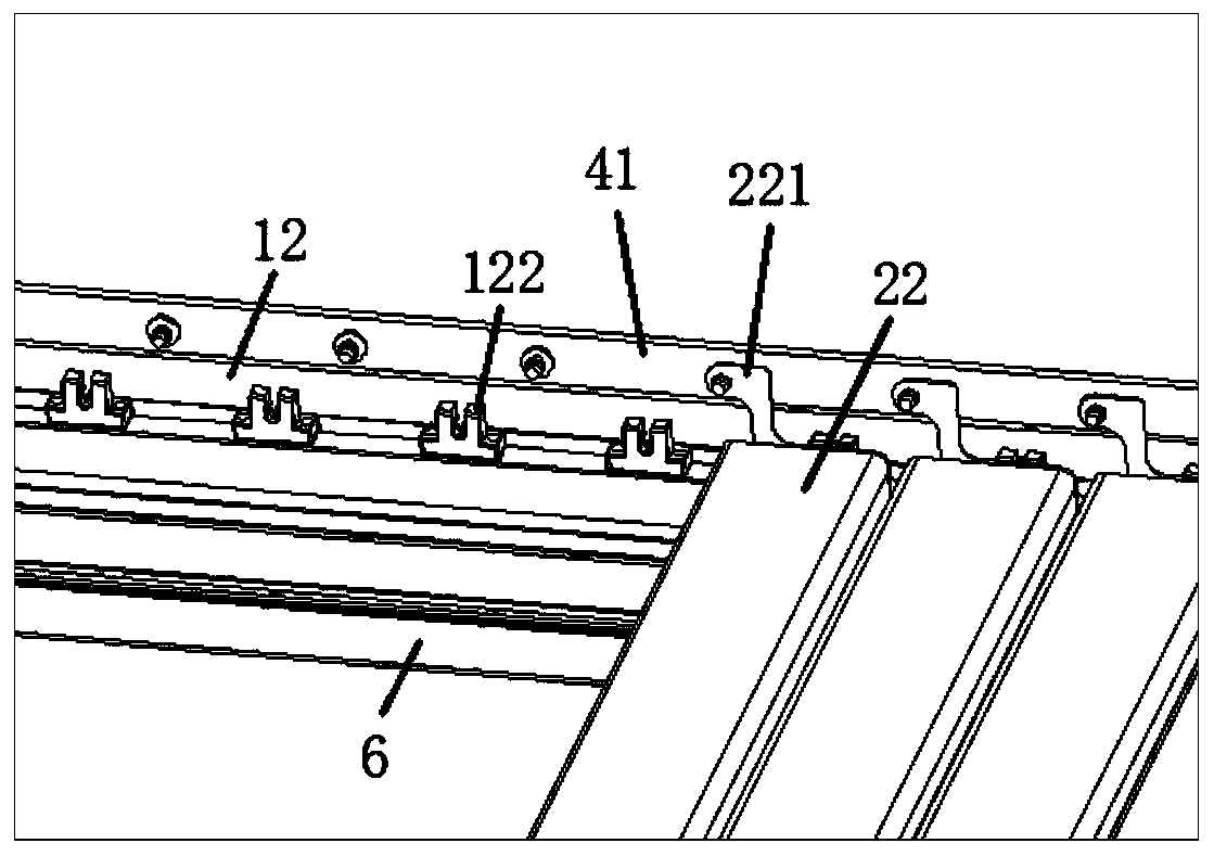
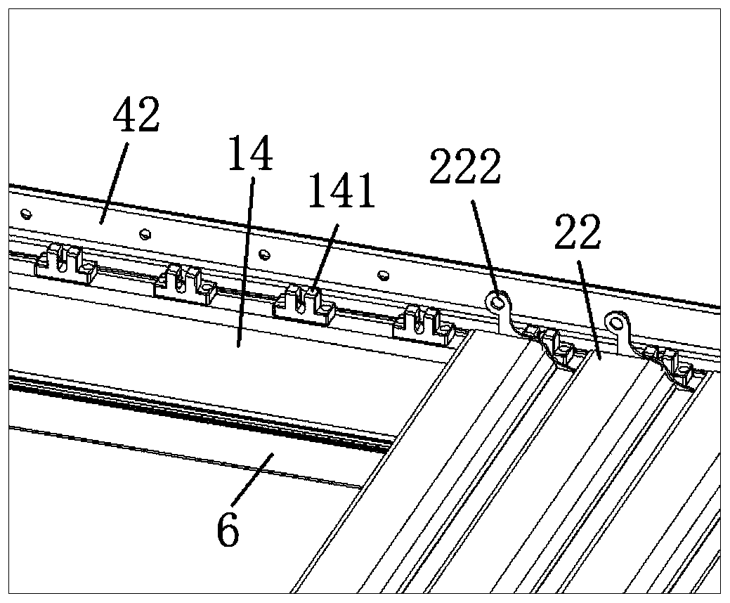
The invention discloses a double-sided flat panel louver canopy. The double-sided flat panel louver canopy comprises a cross beam frame, a plurality of double-sided flat panel louvers, a driving device and a transmission assembly. The cross beam frame comprises a left cross beam and a right cross beam; one end of the driving double-sided flat panel louver is hinged into a left cross beam driving plastic part, and the other end of the driving double-sided flat panel louver is connected with the driving device; and the two ends of the driven double-sided flat panel louver are hinged into a leftcross beam driven plastic part and a right cross beam driven plastic part respectively. The driving device drives the driving double-sided flat panel louver to rotate, and the driving double-sided flat panel louver is connected with the driven double-sided flat panel louver on the basis of the transmission assembly and synchronously rotates. When the double-sided flat panel louvers rotate to be closed, the double-sided flat panel louvers are attached to one another. The double-sided flat panel louver canopy is reasonable in structural design, can cope with severe weather, has the advantages ofbeing easy ad convenient to operate and attractive and harmonious in overall design, and has a good practical use effect.

Description

technical field [0001] The invention relates to the technical field of outdoor sunshade equipment, in particular to a double-sided flat louver awning. Background technique [0002] The venetian awning is a modern craft product, which has the functions of blocking sunlight, blocking ultraviolet radiation, and sheltering from wind and rain, and is widely used in the daily life of the public. [0003] Traditional louver awnings generally have the problems of poor structural materials and unreasonable structural design, and cannot cope with bad weather. They are prone to damage when encountering strong wind and heavy rain, and have the problem of low service life; moreover, the traditional louver awning is easy to operate It is very troublesome and affects the actual use effect of the user; in addition, the overall design of the traditional louver awning is not beautiful and harmonious enough, which affects the user's perception. Contents of the invention [0004] The purpose...

Claims


Application Information

Patent Timeline
Patent Type & Authority Applications(China)
IPC IPC(8): E04H1/12E04B7/16E04D13/04E04D13/064
CPCE04H1/1205E04B7/163E04D13/04E04D13/064E04F10/10
Inventor 方桂平邓圣刚
Owner 广东格绿朗节能科技有限公司
Learn More