
Chip manufacturing based storing device with protective structure

A protective structure and storage device technology, applied in the direction of unloading devices, containers to prevent mechanical damage, packaging, etc., can solve the problems of inconvenient stacking of storage devices, lack of a good protective structure, lack of a good vibration reduction effect, etc., to achieve Reduce the chance of contact with outside air and contact, avoid moisture or oxidation, and facilitate stacking and placement

Inactive Publication Date: 2020-08-28
申启蕾
View PDF13 Cites 4 Cited by
  • Summary
  • Abstract
  • Description
  • Claims
  • Application Information

AI Technical Summary

Problems solved by technology

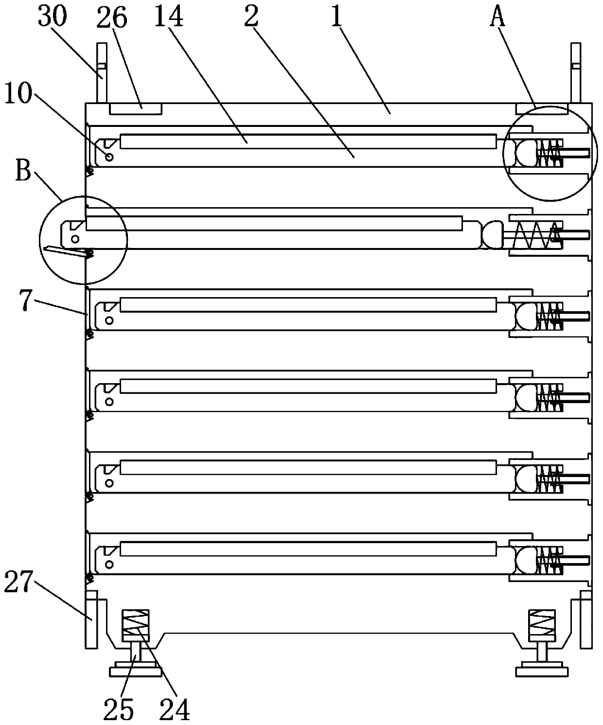
[0005] The object of the present invention is to provide a storage device with a protective structure based on chip manufacturing, to solve the problem that the existing storage device with a protective structure based on chip manufacturing in the above background technology is difficult for similar products to be automatically stored in the chip placement tray. Fixation, lack of a good protective structure, lack of a good vibration reduction effect, and inconvenient stacking of storage devices

Method used


Image

  • Chip manufacturing based storing device with protective structure
  • Chip manufacturing based storing device with protective structure
  • Chip manufacturing based storing device with protective structure

Examples


Embodiment Construction

[0028] The following will clearly and completely describe the technical solutions in the embodiments of the present invention with reference to the accompanying drawings in the embodiments of the present invention. Obviously, the described embodiments are only some, not all, embodiments of the present invention.

[0029] In describing the present invention, it should be understood that the terms "upper", "lower", "front", "rear", "left", "right", "top", "bottom", "inner", " The orientation or positional relationship indicated by "outside", etc. is based on the orientation or positional relationship shown in the drawings, and is only for the convenience of describing the present invention and simplifying the description, rather than indicating or implying that the referred device or element must have a specific orientation, so as to Specific orientation configurations and operations, therefore, are not to be construed as limitations on the invention.

[0030] see Figure 1-8, ...


PUM


Abstract

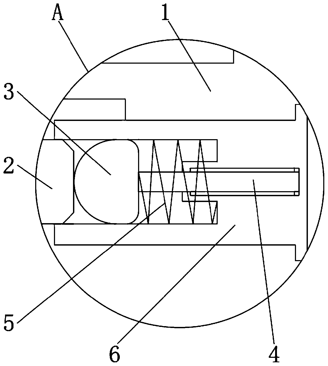
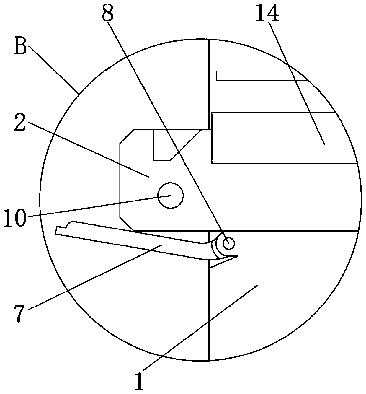
The invention belongs to the technical field of storing devices and particularly relates to a chip manufacturing based storing device with a protective structure. The chip manufacturing based storingdevice comprises a storing device main body and a clamping buckle; a sliding plate is mounted in the storing device main body; a pushing block is arranged on the outer side of the sliding plate; a limiting rod is mounted on the outer wall of the pushing block; a first spring is arranged on the edge side of the limiting rod; a mounting block is mounted on the edge side of the first spring; an opening-closing door is mounted on the outer wall of the storing device main body; a first rotary shaft penetrates through the opening-closing door; a torsional spring is arranged on the edge side of the first rotary shaft; a slot is formed in the outer wall of the sliding plate; a fixture block is mounted on the inner wall of the storing device main body; and a pull rod is arranged on the outer wall of the fixture block. The chip manufacturing based storing device can be automatically fixed after a chip placing disc is accommodated, has a better protective structure and better vibration reducing effect and can be conveniently placed in a superposed manner.

Description

technical field [0001] The invention relates to the technical field of storage devices, in particular to a storage device with a protective structure for chip manufacturing. Background technique [0002] Chips, also known as microcircuits, microchips, integrated circuits, etc., refer to silicon chips containing integrated circuits. They are small in size and have different functions. They are often part of computers or other electronic equipment. Among electronic products used in modern society , is inseparable from the application of the chip, and in chip manufacturing, a dedicated storage device must be used to store the semi-finished or finished chip. [0003] However, there are still some deficiencies in the existing storage devices. After retrieval, the patent application number CN201520285725.X in China discloses a biochip storage device, including an upper cover, a right handle, a magnet, a storage slot, Access port, hinge, lower cover, left handle and iron sheet. T...

Claims


Application Information

Patent Timeline
IPC IPC(8): B65D25/02B65D25/10B65D25/24B65D25/52B65D21/032B65D43/22B65D53/02B65D81/02B65D85/90
CPCB65D25/02B65D25/101B65D25/24B65D25/52B65D21/0228B65D43/22B65D53/02B65D81/02B65D2585/86
Inventor 不公告发明人
Owner 申启蕾
Learn More