Liftable cable rack
A lifting rack and cable rack technology is applied in the field of cargo storage, which can solve the problem of large area for storage of cable trays, and achieve the effects of high practical value, good storage and safe operation.
- Summary
- Abstract
- Description
- Claims
- Application Information
AI Technical Summary
Problems solved by technology
Method used
Image
Examples
Embodiment 1
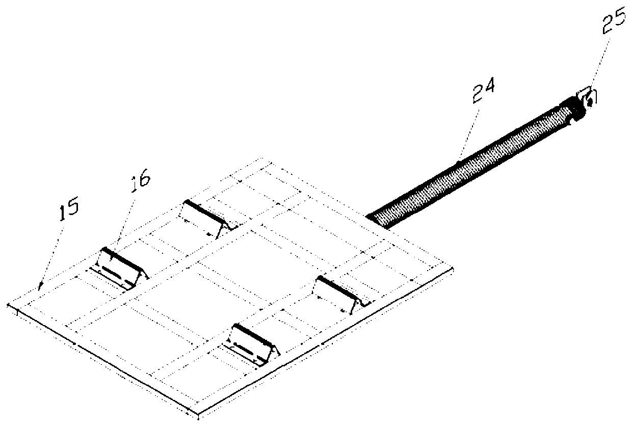
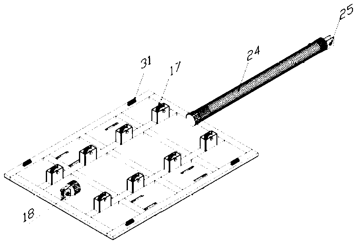
[0026] Embodiment 1: a liftable cable rack, such as figure 1 As shown, it includes base frame 1, transverse moving cable carrier 2, lifting frame 3, sprocket frame 4, chain 5, lifting hydraulic cylinder 6, horizontal hydraulic cylinder 24, hydraulic lock 7, fuel tank, travel switch, sprocket 20 and electrical control system, the bottom of the base frame 1 is installed on the ground through anchor bolts, the lifting frame 3 is slidably installed on the lower part of the base frame 1, the sprocket frame 4 is installed on the upper part of the base frame 1, and the top of the base frame 1 is in contact with the warehouse roof. Then, both sides of the traversing cable carrier 2 are slidingly connected with the lifting frame 3, and the side of the traversing cable carrier 2 facing the base frame 1 is connected with the lifting frame 3 through a horizontal hydraulic cylinder 24, and the two sides of the lifting frame 3 are connected with the lifting frame 3. The base frame 1 is slid...
Embodiment 2
[0032] Embodiment 2, a liftable cable rack. Compared with Embodiment 1, this embodiment adds at least one cable rack, roof track and driving motor. The track is fixedly installed on the roof of the warehouse, and the track is clamped with the cable rack. , the cable rack includes a moving pulley, a connecting bracket and a storage base, the moving pulley is clamped in the track, the upper end of the connecting bracket is connected to the moving pulley, the lower end of the connecting bracket is connected to the storage base, the storage base is used to carry the cable reel, the control end of the drive motor is connected to the electric The control system is connected, the output end of the driving motor is connected with the movable pulley, and the track includes a main track and several sub-tracks, and the several sub-tracks are all connected with the main track, and all the other structures are the same as the first embodiment. Example 1, more cable reels can be stored, and ...
Embodiment 3
[0034] Embodiment three, a liftable cable rack, such as Figure 7 and Figure 8 As shown, compared with Embodiment 1, the present embodiment has increased several adjusting blocks 33 and threaded rods 34, two square grooves are processed on the panel 15, the threaded rods 34 are rotationally connected with the panel 15, and the adjusting blocks 33 are used to cover the square. Slot, the bottom of the adjustment block 33 is provided with an arc groove, the arc groove matches the threaded rod, the arc groove is provided with threads corresponding to the thread rod, the upper part of the adjustment block 33 and one side of the square groove are engraved with scales, and the rest of the structure Same as embodiment one. Compared with Embodiment 1, this embodiment has eight or ten adjustment blocks, and the cable reel is in the correct position when it presses the middle two blocks. You can also check the scale on the adjustment block and the square groove to see if the cable reel...
PUM
 Abstract
Description
Claims
Application Information
 - R&D Engineer
- R&D Manager
- IP Professional
- Industry Leading Data Capabilities
- Powerful AI technology
- Patent DNA Extraction
Browse by: Latest US Patents, China's latest patents, Technical Efficacy Thesaurus, Application Domain, Technology Topic, Popular Technical Reports.
© 2024 PatSnap. All rights reserved.Legal|Privacy policy|Modern Slavery Act Transparency Statement|Sitemap|About US| Contact US: help@patsnap.com


