
Automatic trimming equipment for wind turbine blade girder

A wind power blade, automatic cutting technology, applied in the direction of automatic control devices, metal processing equipment, grinding/polishing equipment, etc., can solve the problems of unfavorable health of employees, low work efficiency, poor manual cutting accuracy, etc., to improve cutting stability High performance and cutting accuracy, avoid manual cutting, reduce the effect of environmental protection pressure

Pending Publication Date: 2020-08-25
国能联合动力技术(保定)有限公司
View PDF0 Cites 4 Cited by
  • Summary
  • Abstract
  • Description
  • Claims
  • Application Information

AI Technical Summary

Problems solved by technology

[0003] At present, the edge trimming of the girder is generally performed manually by employees with hand-held electric cutting machines. As the length of the blade increases, the labor intensity increases and the work efficiency is low.
Long-term cutting operations are prone to work-related accidents and quality accidents
Moreover, according to the design, the width of the blade tip of the girder gradually changes from wide to narrow, and the accuracy of manual cutting is poor
At the same time, a large amount of dust will be generated when the beam is cut, which will pollute the environment and is not conducive to the health of employees

Method used


Image

  • Automatic trimming equipment for wind turbine blade girder
  • Automatic trimming equipment for wind turbine blade girder

Examples


Embodiment Construction

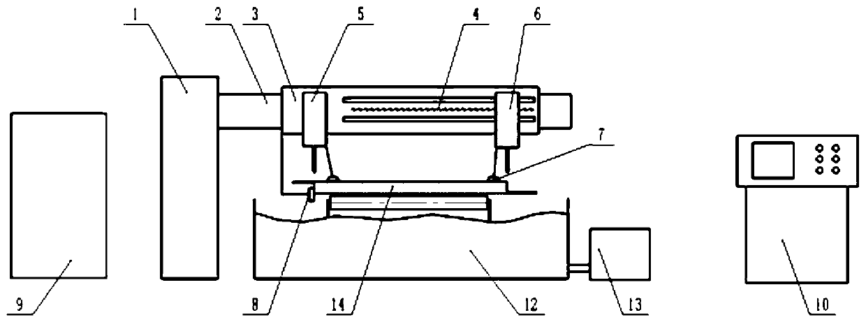
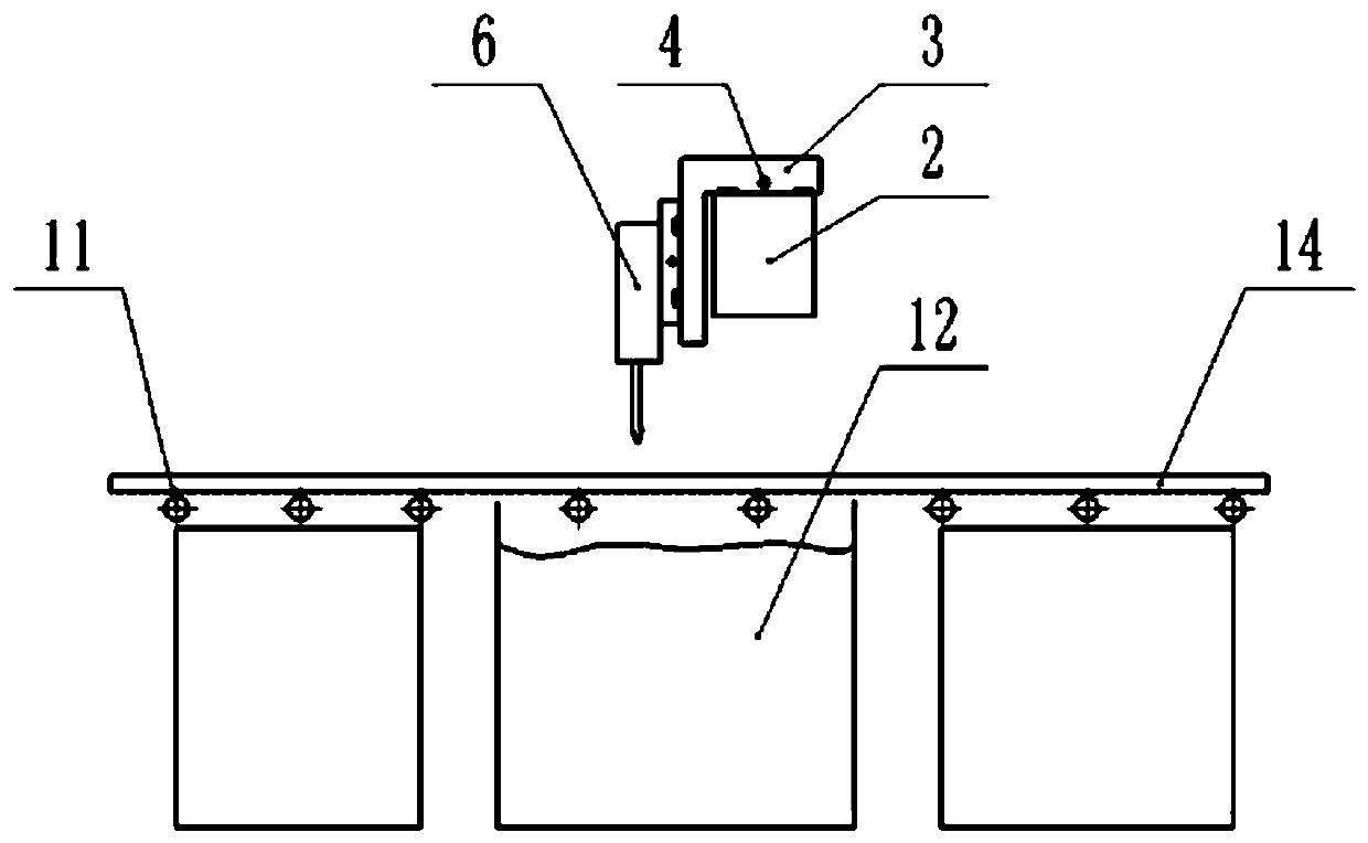
[0015] In order to better understand the purpose, structure and function of the present invention, a wind power blade girder automatic trimming device of the present invention will be further described in detail in conjunction with the accompanying drawings.

[0016] Such as Figure 1 to Figure 2 As shown, it is shown as a wind power blade girder automatic edge trimming device of the present invention, comprising a transverse guide rail 2, suspended above the girder 14 to be cut on the conveying platform 11, and fixed to the ground through the frame 1 connected by the side, and The length direction of guide rail 2 is provided with slide table 3 that can move left and right, slide table 3 is provided with fixed cutter head 5, movable cutter head guide rail 4, fixed cutter head 5 is positioned at the left side of slide table 3, and the right The side is provided with a movable cutter head 6, and the fixed cutter head 5 and the movable cutter head 6 can move up and down, and the ...


PUM


Abstract

The invention discloses automatic trimming equipment for a wind turbine blade girder. The automatic trimming equipment comprises a transverse guide rail, a sliding table, a fixed cutter head, a movable cutter head and a sensing detection system, wherein the transverse guide rail is located on a to-be-cut girder; the sliding table is arranged in the length direction of the transverse guide rail, the fixed cutter head and a movable cutter head guide rail are arranged on the sliding table; the fixed cutter head and the movable cutter head can move up and down, the fixed cutter head is arranged onthe left side of the sliding table, and the movable cutter head is arranged on the movable cutter head guide rail and can move left and right relative to the fixed cutter head; and the sensing detection system is connected with the sliding table, the fixed cutter head and the movable cuter head and used for detecting the position of the girder, and the sliding table, the fixed cutter head and themovable cutter head are correspondingly controlled to move according to the detected signals, so that the to-be-cut girder is cut freely. The automatic trimming equipment can operate automatically, produces no dust and is high in cutting accuracy; two sides of front and back edges of the girder are cut simultaneously, and the working efficiency is high; the automatic trimming equipment senses andcontrols the cutting width, cuts the girders with different widths and has a wide applicable range; and quality accidents and safety accidents such as cut wounds of workers are avoided.

Description

technical field [0001] The invention relates to the field of wind power blade girders, in particular to an automatic edge trimming device for wind power blade girders. Background technique [0002] There is a girder on the windward side and the leeward side of the wind turbine blade. The girder needs to be prefabricated on a proprietary mold and trimmed before being used in the production of the blade. Each girder needs to cut off the excess scrap on the two sides of the front and rear edges. [0003] At present, the edge trimming of the girder is generally performed manually by employees with hand-held electric cutting machines. As the length of the blade increases, the labor intensity increases and the work efficiency is low. Long-term cutting operations are prone to work-related accidents and quality accidents. Moreover, according to the design, the width of the blade tip of the girder gradually changes from wide to narrow, and the accuracy of manual cutting is poor. A...

Claims


Application Information

Patent Timeline
IPC IPC(8): B23Q9/00B23Q15/02B23Q7/00B24C3/06B24C3/32B24C5/00
CPCB23Q7/00B23Q9/0042B23Q15/02B24C3/06B24C3/32B24C5/00
Inventor 刘广刘梅赵亚男朱保伟何占启姜宏业
Owner 国能联合动力技术(保定)有限公司
Learn More