
Laminating jig and method for manufacturing display module by adopting laminating jig

A bonding fixture and bonding technology, which is applied in semiconductor/solid-state device manufacturing, semiconductor devices, electrical components, etc., can solve problems such as cracks easily appearing around the hole in the display panel, and achieve the goal of preventing cracks and avoiding stress concentration Effect

Active Publication Date: 2020-08-21
BOE TECH GRP CO LTD +1
View PDF5 Cites 2 Cited by
  • Summary
  • Abstract
  • Description
  • Claims
  • Application Information

AI Technical Summary

Problems solved by technology

[0004] In view of this, the present application provides a bonding fixture and a method for manufacturing a display module, which are used to solve the problem that cracks tend to appear around the hole in the display panel in the prior art when the display panel is bonded to the cover glass. question

Method used


Image

  • Laminating jig and method for manufacturing display module by adopting laminating jig
  • Laminating jig and method for manufacturing display module by adopting laminating jig
  • Laminating jig and method for manufacturing display module by adopting laminating jig

Examples


Embodiment Construction

[0033] Exemplary embodiments of the present disclosure will be described in more detail below with reference to the accompanying drawings. Although exemplary embodiments of the present disclosure are shown in the drawings, it should be understood that the present disclosure may be embodied in various forms and should not be limited by the embodiments set forth herein. Rather, these embodiments are provided for more thorough understanding of the present disclosure and to fully convey the scope of the present disclosure to those skilled in the art.

[0034] Those skilled in the art will understand that unless otherwise stated, the singular forms "a", "an", "said" and "the" used herein may also include plural forms. It should be further understood that the word "comprising" used in the specification of the present application refers to the presence of the features, integers, steps, operations, elements and / or components, but does not exclude the presence or addition of one or mor...


PUM


Abstract

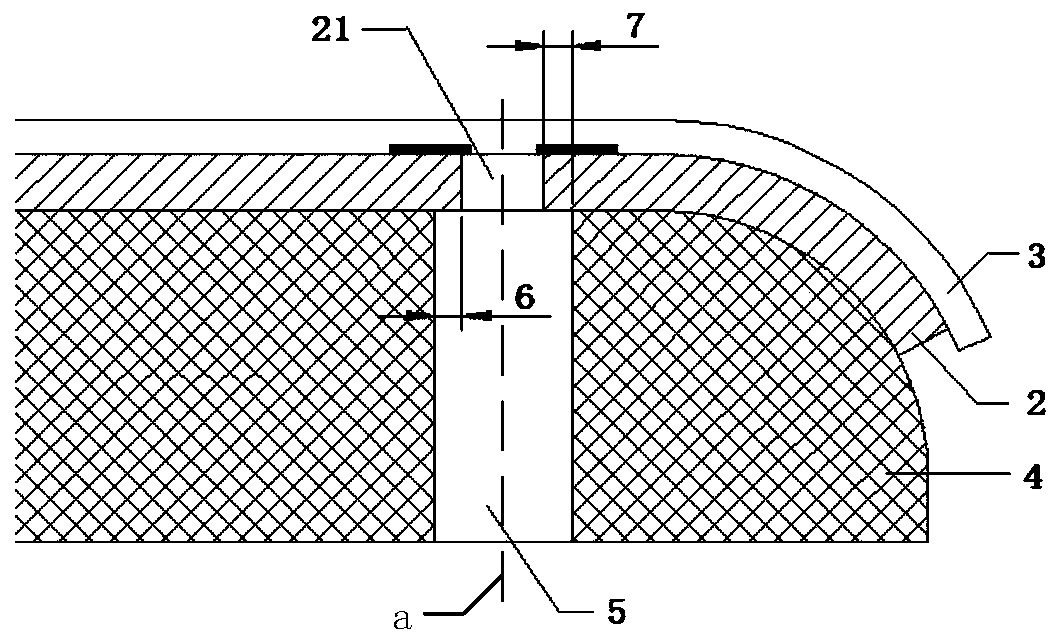
The invention provides a laminating jig and a method for manufacturing a display module by adopting the laminating jig. The laminating jig comprises a gasket part and a through hole penetrating through the gasket part. The position of the through hole is matched with the position of an open hole, and the through hole covers the open hole in the orthographic projection area of the display panel. According to the embodiment of the invention, the through hole is formed in the gasket part; the through hole is formed in the display panel, the position of the through hole is matched with that of theopen hole, the through hole covers the open hole in the orthographic projection area of the display panel, the pressure borne by the open hole area of the display panel is reduced by structure, the phenomenon of stress concentration around the open hole is avoided, and cracks around the hole are prevented.

Description

technical field [0001] The present application relates to the field of display technology, specifically a bonding fixture and a method for manufacturing a display module using the bonding fixture. Background technique [0002] As people's requirements for mobile terminals such as mobile phones are increasing day by day, full screens have become the design direction of mainstream mobile phone screens. In order to achieve a full screen, at present, the display panel punching solution has become one of the solutions for the under-screen camera hole technology. [0003] After the organic light-emitting diode flexible display panel undergoes a laser drilling process, the edge structure of the hole is relatively fragile. When the display panel is attached to the cover glass, a silicone pad is usually required to support the display panel and the cover plate. However, the applicant found that , The conventional silicone pad squeezes the periphery of the hole to cause stress concen...

Claims


Application Information

Patent Timeline
Patent Type & Authority Applications(China)
IPC IPC(8): H01L51/56H01L27/32H01L51/52
CPCH10K59/00H10K50/84H10K71/00
Inventor 曾利卿馨汤强
Owner BOE TECH GRP CO LTD
Learn More