
Monitoring and detecting equipment with remote control structure for social safety

A detection equipment and safety technology, which is applied in the field of social security, can solve the problems of unsuitable fire detection, inconvenient and flexible internal assembly, poor practical performance, etc., to change the detection effect and range, and extend the relative horizontal distance , Improve the effect of stability performance

Inactive Publication Date: 2020-08-21
DONGGUAN KAILEDI NUMERICAL CONTROL SCI & TECH CO LTD
View PDF0 Cites 0 Cited by
  • Summary
  • Abstract
  • Description
  • Claims
  • Application Information

AI Technical Summary

Problems solved by technology

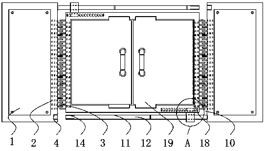
[0004] The purpose of the present invention is to provide a monitoring and testing device with a remote control structure for social security, so as to solve the problem that the existing testing equipment proposed in the above-mentioned background technology is not well segmented and used at the side and the middle. Three-segment connection, layered, and variable range detection, which leads to its inability to perform fire detection well, and there is a situation of poor practical performance, and there are also internal assembly connections when it is used. Not enough convenience and flexibility

Method used


Image

  • Monitoring and detecting equipment with remote control structure for social safety
  • Monitoring and detecting equipment with remote control structure for social safety
  • Monitoring and detecting equipment with remote control structure for social safety

Examples


Embodiment Construction

[0026] The following will clearly and completely describe the technical solutions in the embodiments of the present invention with reference to the accompanying drawings in the embodiments of the present invention. Obviously, the described embodiments are only some, not all, embodiments of the present invention.

[0027] In the description of the present invention, unless otherwise stated, the meaning of "plurality" is two or more; the terms "upper", "lower", "left", "right", "inner", "outer" , "front end", "rear end", "head", "tail", etc. indicate the orientation or positional relationship based on the orientation or positional relationship shown in the drawings, and are only for the convenience of describing the present invention and simplifying the description, rather than Indicates or implies that the device or element referred to must have a particular orientation, be constructed and operate in a particular orientation, and therefore should not be construed as limiting the...


PUM


Abstract

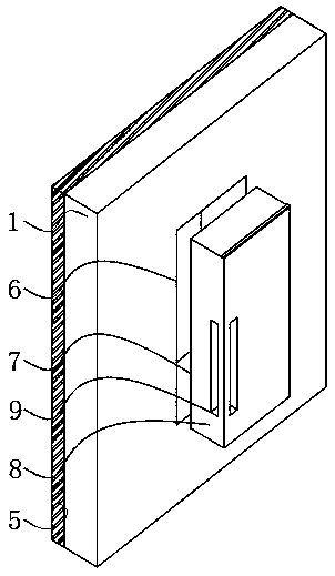
The invention relates to monitoring and detecting equipment with a remote control structure for social safety. The monitoring and detecting equipment comprises a detection box and a center box; clamping holes are formed in the side wall of the detection box; cooling fins are arranged at the side ends of the clamping holes; a screw interface is formed in the bottom end wall of the detection box ina penetrating manner; a rubber wall is fixed on the inner side of the middle of the detection box; a through hole is formed in the left end wall of the detection box; a sealing mechanism is mounted atthe inner end of the penetrating opening; the central box is arranged on the inner side of the detection box; limiting mechanisms are mounted at the upper end and the lower end of the central box; the beneficial effects are a limiting rod moves relative to a terminating seat, the effect of prolonging the relative horizontal distance between the limiting rod and the central box can be achieved,the detection box and the center box can be extended conveniently, the application range of the detection box is adjusted, then the purpose of changing the detection effect and range is achieved, andthe detection operation of the monitoring and detecting equipment for social safety can be completed better and conveniently.

Description

technical field [0001] The invention relates to the technical field of social security, in particular to a monitoring and testing device with a remote control structure for social security. Background technique [0002] Social security is a comprehensive index to measure the four basic aspects of social security in a country or region, including social security (measured by the criminal crime rate per 10,000 people), traffic safety (measured by the death rate of traffic accidents per million people), life Safety (measured by the death rate of fire accidents per million people) and production safety (measured by the death rate of per million man-made accidents), in which monitoring and testing equipment is generally used in fire prevention to prevent problems before they happen effect. [0003] Because the existing detection equipment does not use the side end and the middle section well, it is allowed to connect in three sections, and detect in layers and variable ranges, w...

Claims


Application Information

Patent Timeline
Patent Type & Authority Applications(China)
IPC IPC(8): G01D21/00G01D11/16G01D11/24B65D25/02B65D53/00B65D81/26
CPCB65D25/02B65D53/00B65D81/26G01D11/16G01D11/24G01D21/00
Inventor 文婵邱广文陈马鑫
Owner DONGGUAN KAILEDI NUMERICAL CONTROL SCI & TECH CO LTD
Learn More