
Induction heating pickling tank

An induction heating and induction heating coil technology, applied in the field of pickling tanks, can solve the problems of slow heating speed, short service life, serious energy consumption, etc., and achieve the effects of easy temperature, long service life and good heating effect

Pending Publication Date: 2020-08-21
宝武特冶航研科技有限公司
View PDF12 Cites 1 Cited by
  • Summary
  • Abstract
  • Description
  • Claims
  • Application Information

AI Technical Summary

Problems solved by technology

Regardless of the resistance heating element heating or external steam heating method, the heating speed is slow, the conversion and utilization of electric energy or heat energy is low, and the energy consumption is serious. The temperature to be maintained in the washing solution
At the same time, the resistance heating element or the steam heat exchange element must be installed on the inner end surface or the lower end of the pickling tank, and cannot be installed arbitrarily. It occupies a very large space in the pickling tank, which reduces the effective working space of the pickling tank and affects the pickling tank. Tank loading
Moreover, the pickling solution is highly corrosive, and the resistance heating element or steam heat exchange element is built in the pickling tank, which is often corroded and thus has a short service life.
Its replacement or maintenance needs to discharge all the pickling liquid and then replace the heating or heat exchange elements, which directly affects the pickling process, the safety system is low, and it is not conducive to continuous production
Therefore need a kind of induction heating pickling tank to solve the problem of slow pickling speed

Method used


Image

  • Induction heating pickling tank
  • Induction heating pickling tank

Examples


Embodiment Construction

[0025] The present invention will be further described in detail below in conjunction with the accompanying drawings.

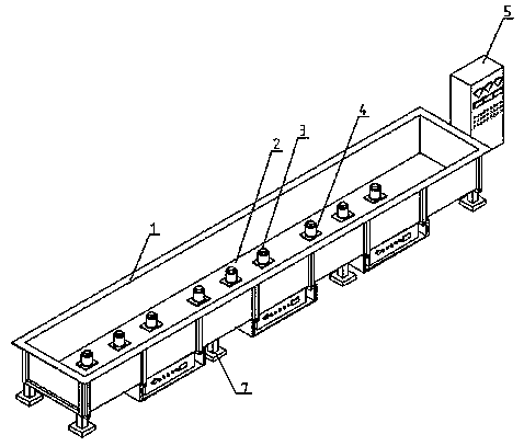
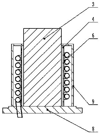
[0026] The reference signs in the accompanying drawings include: pickling tank 1, bottom plate 2, heating block 3, inner casing 4, AC control cabinet 5, induction heating coil 6, support base 7, mounting plate 8, outer casing 9.

[0027] A kind of induction heating pickling tank in this specific embodiment, as figure 1 and figure 2 As shown, it includes a non-metallic pickling tank 1, the non-metallic pickling tank 1 is a rectangular tank body with an upper opening, the tank body includes a horizontal bottom plate 2 and vertical side plates, and the upper surface of the bottom plate 2 is along its length A plurality of vertically extending outer sleeves 9 are provided at the distance between directions, and an inner sleeve 4 that is concentric with the centerline and spaced apart from the outer sleeve 9 is arranged inside the outer sleeve 9. Both the outer ...


PUM


Abstract

The invention discloses an induction heating pickling tank. The induction heating pickling tank comprises a non-metal pickling tank body which refers to a rectangular tank body with the upper portionbeing opened. The tank body comprises a horizontal base plate and vertical side plates. A plurality of outer casing pipes which extend in the vertical direction are arranged on the upper surface of the base plate in the length direction of the base plate at intervals. Inner casing pipes are arranged inside the corresponding outer casing pipes, and the inner casing pipes and the outer casing pipesshare the same center lines and are further arranged in a spaced mode. Both the outer casing pipes and the inner casing pipes are non-metal pipe bodies, and the lower ends of the outer casing pipes and the lower ends of the inner casing pipes are fixed to the base plate in a sealing mode. Heating blocks capable of being in sliding fit with the inner casing pipes in the center line directions of the inner casing pipes are inserted into the corresponding inner casing pipes. The pipe bodies of the inner casing pipes are sleeved with induction heating coils. The upper ends of the inner casing pipes and the upper ends of the outer casing pipes are connected together in a sealing mode. The induction heating coils are electrically connected with an alternating current power source and can generate a high-frequency alternating magnetic field after being powered up so that the heating blocks on the inner sides of the induction heating coils can be heated to heat a pickling solution in the tankbody. By adoption of the induction heating pickling tank disclosed in the invention, the heating speed of the pickling solution in the tank is high, the temperature can be controlled easily and maintenance is also made easy.

Description

technical field [0001] The invention relates to the technical field of pickling tanks, in particular to an induction heating pickling tank. Background technique [0002] The pickling tank is a container used to hold the pickling solution and remove oxides on the inner surface during the pickling process of the pipe. In the pipe production industry, it is mainly used for pickling the inner and outer surfaces of pipes to remove oil, rust, and scale. The pickling tank needs to be heated during the working process to keep the temperature constant within a certain range. The existing pickling tank heating device uses resistance heating element heating or external steam heating method, relying on resistance heating. Heating elements or steam heat conduction increase the temperature of the pickling solution. Regardless of the resistance heating element heating or external steam heating method, the heating speed is slow, the conversion and utilization of electric energy or heat en...

Claims


Application Information

Patent Timeline
IPC IPC(8): C23G3/00
CPCC23G3/00Y02P10/25
Inventor 吴建军李翼飞杨飞
Owner 宝武特冶航研科技有限公司
Learn More