A method and device for producing synthesis gas by plasma-catalyzed dry reforming of methane

A methane dry reforming and plasma technology, applied in chemical instruments and methods, hydrogen/synthesis gas production, inorganic chemistry, etc., can solve problems such as catalyst deactivation, complex devices, pipeline blockage, etc., to improve selectivity, prolong Longevity, easy-to-control effects

Active Publication Date: 2021-11-19
CHINA PETROLEUM & CHEM CORP +1
View PDF1 Cites 0 Cited by
  • Summary
  • Abstract
  • Description
  • Claims
  • Application Information

AI Technical Summary

Problems solved by technology

At present, this technology mainly adopts catalytic reforming method, but this method needs to be carried out under high temperature and high pressure; the device is complex and energy-consuming; carbon deposits are easy to occur, leading to catalyst deactivation and pipeline blockage

Method used


Image

  • A method and device for producing synthesis gas by plasma-catalyzed dry reforming of methane
  • A method and device for producing synthesis gas by plasma-catalyzed dry reforming of methane
  • A method and device for producing synthesis gas by plasma-catalyzed dry reforming of methane

Examples


Embodiment 1

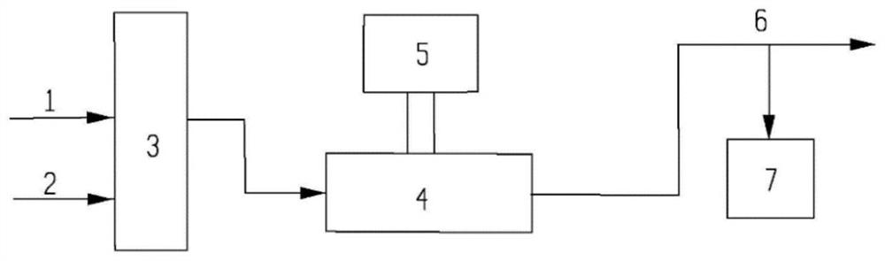
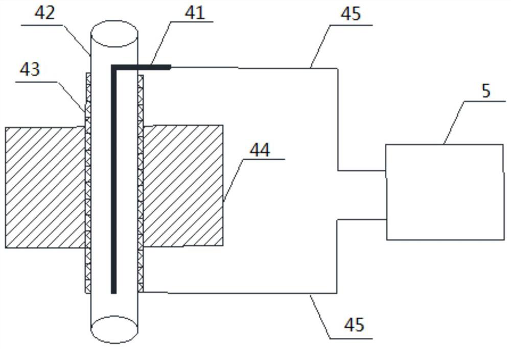
[0077] The reaction pressure is 140kPa (absolute pressure), the flow rate of carbon dioxide 1 is 0.5L / min, and the flow rate of methane 2 is 1.5L / min. After mixing, it enters the ionization chamber of the low-temperature plasma reactor, and the low-temperature plasma reactor is filled with alumina with a diameter of 3mm. Small balls (supporting metal silver 2.5wt%), the heating furnace 44 outside the low-temperature plasma reactor is kept at 260° C., and the low-temperature plasma power supply 5 is connected to perform dielectric barrier discharge. The low-temperature plasma reactor adopts a needle-cylinder electrode structure, and the cylindrical barrier medium is made of ceramics with an outer diameter of 25 mm and an inner diameter of 20 mm. The ground electrode 43 is an annular stainless steel mesh, and the high-voltage electrode 41 is a stainless steel rod with a diameter of 8 mm. The (discharge distance) is 6 mm, and the effective discharge length of the low-temperature p...

Embodiment 2

[0080] The difference from Example 1 is only that the discharge distance is 10 mm.

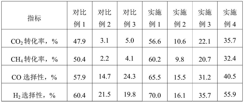
[0081] The reaction results are: the carbon dioxide conversion rate is 10.6%, the methane conversion rate is 9.8%, the carbon monoxide selectivity is 15.5%, and the hydrogen selectivity is 16.1%. After reacting for 48 hours, a small amount of carbon was deposited on the catalyst. The catalyst can still maintain the reactivity after regeneration.

Embodiment 3

[0083] The difference from Embodiment 1 is only that the input power is 100W.

[0084] The reaction results are: the carbon dioxide conversion rate is 22.1%, the methane conversion rate is 20.7%, the carbon monoxide selectivity is 31.2%, and the hydrogen selectivity is 35.7%. After reacting for 48 hours, a small amount of carbon was deposited on the catalyst. The catalyst can still maintain the reactivity after regeneration.


PUM

PropertyMeasurementUnit
particle diameteraaaaaaaaaa

Abstract

The invention discloses a method and a device for producing synthesis gas by plasma catalytic methane dry reforming, and belongs to the technical field of methane and carbon dioxide reforming. The method includes: reacting carbon dioxide and methane under the coupled action of low-temperature plasma and a catalyst to generate synthesis gas mainly composed of carbon monoxide and hydrogen. This process can carry out reforming of methane and carbon dioxide at a lower reaction temperature and lower reaction pressure, reducing energy consumption of the device; supplementing the heat of the reaction unit through the heating furnace, it is easier to control the reaction depth and the conversion rate of raw materials, Does not produce a large amount of carbon deposits, thus prolonging the life of the catalyst. The device used includes a raw material gas distribution unit and a reaction unit. The gas outlet of the raw material gas distribution unit is connected to the inlet of the reaction unit. An ionization chamber is formed between the two electrodes in the reaction unit, and an insulating medium is arranged in the ionization chamber. The heating furnace is surrounded by the ground electrode, and the two electrodes are used for electrical connection with the low-temperature plasma power supply.

Description

technical field [0001] The invention relates to the technical field of methane and carbon dioxide reforming, in particular to a method and device for producing synthesis gas by plasma catalytic methane dry reforming. Background technique [0002] Methane and carbon dioxide are typical greenhouse gases. The development of methane carbon dioxide reforming (also known as methane dry reforming) to synthesis gas technology can not only reduce greenhouse gas emissions, but also turn waste into treasure, and obtain chemical intermediate products with economic value. So it has a double meaning. At present, this technology mainly adopts catalytic reforming method, but this method needs to be carried out under high temperature and high pressure; the device is complex and energy-consuming; carbon deposits are easy to occur, leading to catalyst deactivation and pipeline blockage. [0003] In view of this, the present invention is proposed. Contents of the invention [0004] One of t...

Claims


Application Information

Patent Timeline
Patent Type & Authority Patents(China)
IPC IPC(8): C01B3/40
CPCC01B3/40C01B2203/1041C01B2203/1058C01B2203/1082
Inventor 经铁韩海波孙欢欢王洪彬周文琳亚飞庞晓飞付强
Owner CHINA PETROLEUM & CHEM CORP
Why Eureka
Try Eureka