
Vehicle moving auxiliary method, device and system

An auxiliary system and vehicle technology, applied in the field of vehicles, can solve the problems of restricting the use scenarios of remote control remote control vehicles, not having them, and high risk factors.

Inactive Publication Date: 2020-08-18
NEOLIX TECH CO LTD
View PDF9 Cites 1 Cited by
  • Summary
  • Abstract
  • Description
  • Claims
  • Application Information

AI Technical Summary

Problems solved by technology

However, corresponding to vehicles positioned for self-driving, self-driving vehicles generally do not have steering wheels, accelerator brakes and other control devices, and there is no good way to move the vehicle when the self-driving system of the self-driving vehicle crashes
[0003] At present, when the automatic driving system of the self-driving vehicle fails, the hand-held remote control can be used to remotely control the self-driving vehicle to realize the movement of the self-driving vehicle when the vehicle fails. However, using the remote control to remotely control the receiving end requires the installation of corresponding driver software on the receiving end. The receiving end is required, that is, the self-driving running platform of the self-driving vehicle does not crash. When the self-driving running platform of the self-driving vehicle crashes, it is not feasible to use the remote control to control the vehicle, which severely limits the usage scenarios of using the remote control to control the vehicle
In addition, in the process of using the hand-held remote control to remotely control the self-driving vehicle, the horizontal and vertical movement of the self-driving vehicle needs to be controlled by the buttons on the remote control. However, there is often a large difference between the behavior of the car and the human experience. The use of the remote control to control the failure of the self-driving vehicle requires a lot of training for the operator, and the risk factor in the process of moving the car is high

Method used


Image

  • Vehicle moving auxiliary method, device and system
  • Vehicle moving auxiliary method, device and system
  • Vehicle moving auxiliary method, device and system

Examples


Embodiment Construction

[0047] In order to more clearly understand the above objects, features and advantages of the present disclosure, the solutions of the present disclosure will be further described below. It should be noted that, in the case of no conflict, the embodiments of the present disclosure and the features in the embodiments can be combined with each other.

[0048] In the following description, many specific details are set forth in order to fully understand the present disclosure, but the present disclosure can also be implemented in other ways than described here; obviously, the embodiments in the description are only some of the embodiments of the present disclosure, and Not all examples.

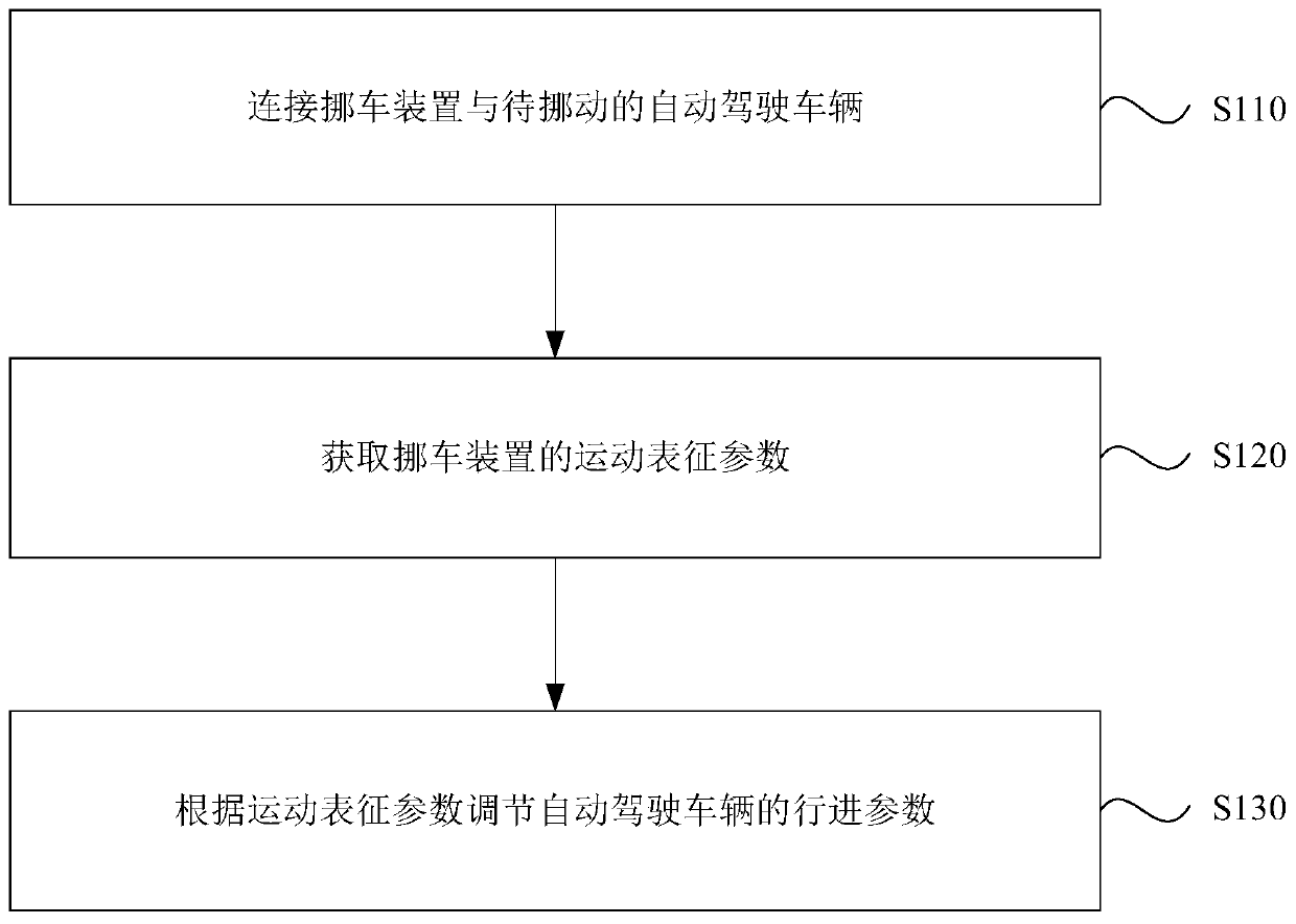
[0049] figure 1 It is a schematic flow chart of a vehicle maneuver assisting method provided by an embodiment of the present disclosure. The vehicle steering assisting method can be applied in an application scenario where a faulty vehicle needs to be steered, and can be executed by the vehicle...


PUM


Abstract

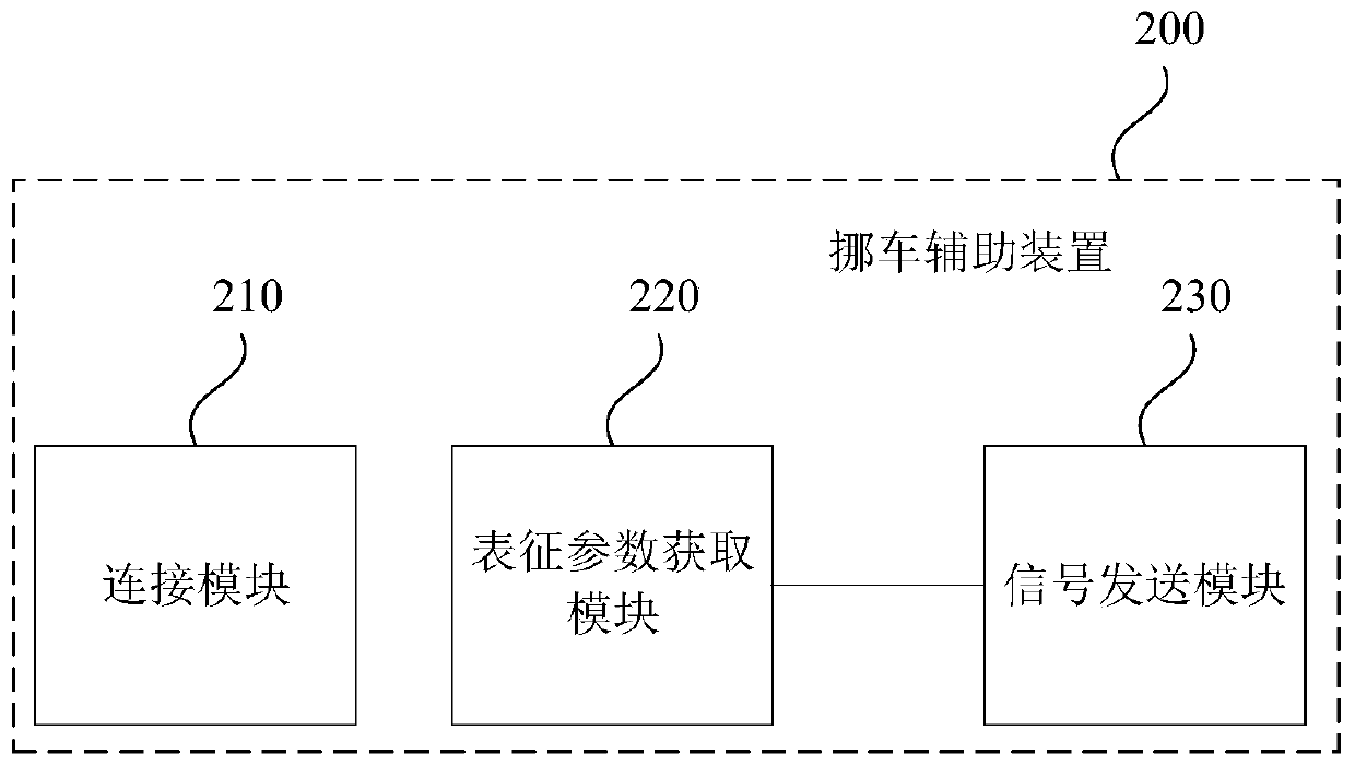
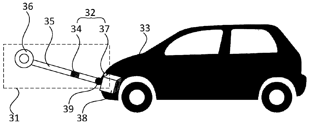
The invention relates to a vehicle moving auxiliary method, a device and a system, and relates to the field of unmanned vehicles (automatic driving or unmanned driving), and the vehicle moving auxiliary method comprises the steps: connecting a vehicle moving device with a to-be-moved automatic driving vehicle; acquiring motion characterization parameters of the vehicle moving device; and adjustingthe advancing parameters of the automatic driving vehicle according to the motion characterization parameters. By means of the method, the faulted automatic driving vehicle can be conveniently and visually moved, the structure is simple, deployment is convenient, learning cost is not needed, starting is fast, efficiency is high, and the difficulty of moving the faulted automatic driving vehicle by personnel or trailers can be reduced.

Description

technical field [0001] The present disclosure relates to the technical field of vehicles, and in particular to a vehicle steering assisting method, device and system. Background technique [0002] For self-driving vehicles refitted from traditional vehicles, they generally retain control devices such as steering wheels and accelerator brakes. When the automatic driving system of the self-driving vehicle breaks down, personnel can take over the self-driving vehicle for maneuvering operations. However, corresponding to vehicles positioned for self-driving, self-driving vehicles generally do not have steering wheels, accelerator brakes and other control devices, and there is no good way to move the vehicle when the self-driving system of the self-driving vehicle crashes. [0003] At present, when the automatic driving system of the self-driving vehicle fails, the hand-held remote control can be used to remotely control the self-driving vehicle to realize the movement of the sel...

Claims


Application Information

Patent Timeline
IPC IPC(8): B60W30/18
CPCB60W30/18009
Inventor 王永聪
Owner NEOLIX TECH CO LTD
Learn More