
Laser cutting machine with movable protective surface for cage and cutting process

A laser cutting machine, laser cutting head technology, applied in laser welding equipment, manufacturing tools, metal processing equipment, etc. Safety is not guaranteed, etc., to achieve the effect of improving safety performance, increasing the rotatable range, and good stability

Active Publication Date: 2022-05-31
WUXI YITONG PRECISION MACHINERY
View PDF10 Cites 0 Cited by
  • Summary
  • Abstract
  • Description
  • Claims
  • Application Information

AI Technical Summary

Problems solved by technology

[0004] A wind power generation bearing cage manufacturing equipment disclosed in the Chinese invention patent application publication CN209288712U, although the wind power generation bearing cage manufacturing equipment uses coiled plates as raw materials for processing, and controls accurate step-by-step continuous feeding, Improve the position accuracy of cutting, reduce the welding interface, improve production efficiency and production accuracy, and reduce production costs. However, the structural design of the laser cutting unit of this wind power generation bearing cage manufacturing equipment is very common and does not have clamping , the function of fixing the workpiece, and does not have a movable and flexible protective structure, and the safety cannot be guaranteed

Method used


Image

  • Laser cutting machine with movable protective surface for cage and cutting process
  • Laser cutting machine with movable protective surface for cage and cutting process
  • Laser cutting machine with movable protective surface for cage and cutting process

Examples


Embodiment Construction

[0052] The following will clearly and completely describe the technical solutions in the embodiments of the present invention with reference to the accompanying drawings in the embodiments of the present invention. Obviously, the described embodiments are only some, not all, embodiments of the present invention.

[0053] In the description of the present invention, unless otherwise stated, the meaning of "plurality" is two or more; the terms "upper", "lower", "left", "right", "inner", "outer" , "front end", "rear end", "head", "tail", etc. indicate the orientation or positional relationship based on the orientation or positional relationship shown in the drawings, and are only for the convenience of describing the present invention and simplifying the description, rather than Nothing indicating or implying that a referenced device or element must have a particular orientation, be constructed, and operate in a particular orientation should therefore not be construed as limiting ...


PUM


Abstract

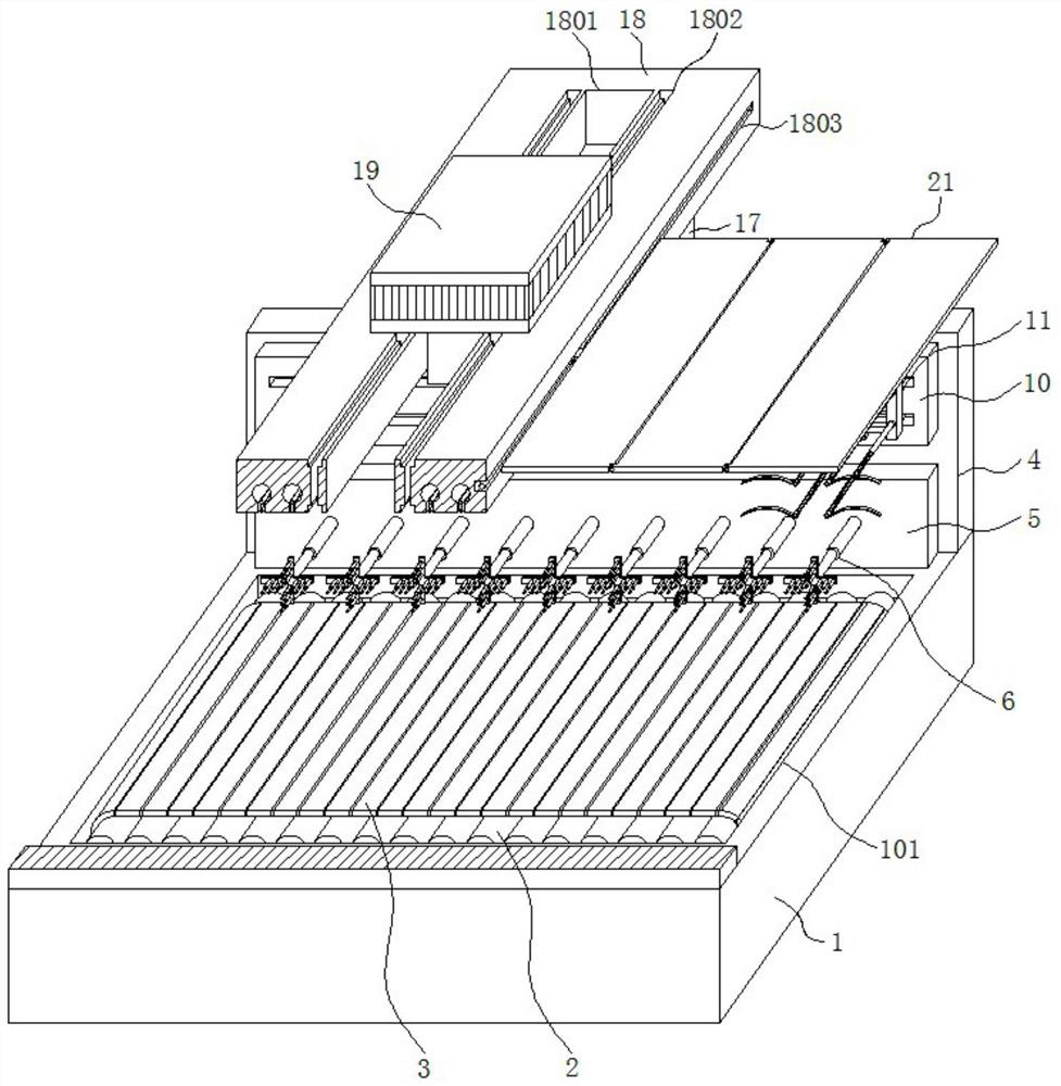
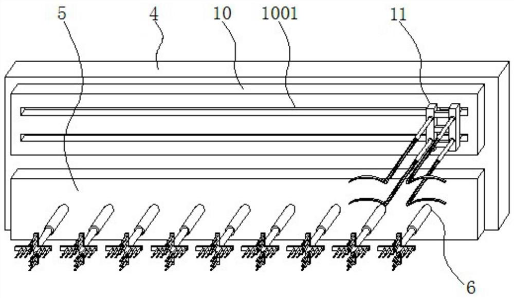
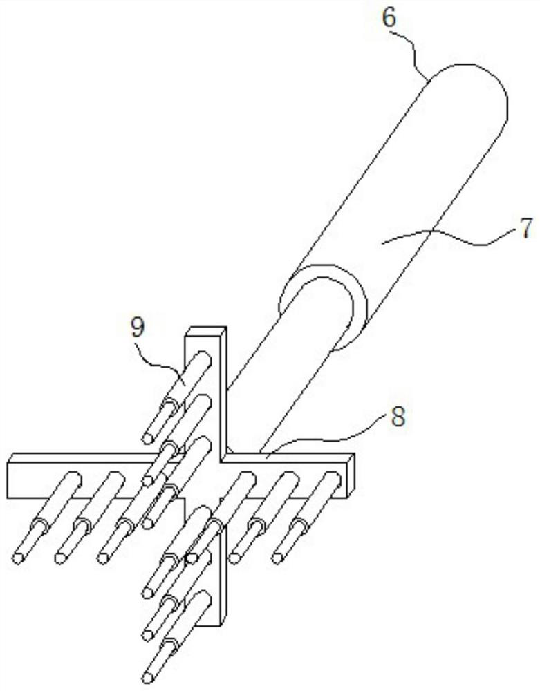
The invention discloses a laser cutting machine with a movable protective surface for a cage and a cutting process, and relates to the technical field of laser cutting of cages, specifically a base, a supporting mechanism, a supporting mechanism and a protective door assembly. The middle part of the upper surface is provided with a placement groove, and the outer part of the middle section of the conveying roller is provided with a conveying crawler as a whole. The supporting mechanism is arranged equidistantly on the lower mounting plate. The door assembly is mounted on the top plate by screw rods. The cage uses a laser cutting machine with a movable protective surface and the cutting process. Through the setting of the protective door assembly, the safety performance of the laser cutting machine is effectively improved. With the protective door assembly moving together, the protective door assembly can be bent downward under the action of the connecting shaft, so that the laser cutting position can be blocked to avoid safety problems.

Description

technical field [0001] The invention relates to the technical field of laser cutting of a cage, in particular to a laser cutting machine with a movable protective surface for a cage and a cutting process. Background technique [0002] The laser cutting machine focuses the laser emitted from the laser into a high-power-density laser beam through the optical path system. The laser beam irradiates the surface of the workpiece to make the workpiece reach the melting point or boiling point. At the same time, the high-pressure gas coaxial with the beam will melt or Vaporized metal is blown away. Compared with traditional tool cutting, laser cutting has the advantages of high processing precision and fast processing speed. [0003] The cage is a product required for the manufacture of medical equipment. In the production and processing of the cage, it needs to be cut and polished. In order to ensure the processing quality and improve the processing efficiency, modern qualified fact...

Claims


Application Information

Patent Timeline
Patent Type & Authority Patents(China)
IPC IPC(8): B23K26/38B23K26/70
CPCB23K26/38B23K26/70B23K26/702Y02E10/72
Inventor 易阳
Owner WUXI YITONG PRECISION MACHINERY
Learn More