
Automatic balancing device, tomography equipment and automatic balancing method

An automatic balancing and driving unit technology, applied in radiation detection devices, computerized tomography scanners, diagnosis, etc., can solve the problems of single scanning range and narrow scanning image range, so as to increase the imaging area, improve the rotation stability, and expand the scanning The effect of vision

Pending Publication Date: 2020-08-14
武汉中科医疗科技工业技术研究院有限公司
View PDF7 Cites 0 Cited by
  • Summary
  • Abstract
  • Description
  • Claims
  • Application Information

AI Technical Summary

Problems solved by technology

[0003] Based on this, it is necessary to provide an automatic balancing device, a tomographic imaging device and an automatic balancing method for expanding the scanning field of view to solve the problem that the current balancing device has a single scanning range and the scanning image range is narrow

Method used


Image

  • Automatic balancing device, tomography equipment and automatic balancing method
  • Automatic balancing device, tomography equipment and automatic balancing method
  • Automatic balancing device, tomography equipment and automatic balancing method

Examples


Embodiment Construction

[0030] In order to make the purpose, technical solution and advantages of the present invention clearer, the automatic balancing device, tomographic imaging equipment and automatic balancing method of the present invention will be further described in detail through the following examples and in conjunction with the accompanying drawings. It should be understood that the specific embodiments described here are only used to explain the present invention, not to limit the present invention.

[0031] The serial numbers assigned to components in this document, such as "first", "second", etc., are only used to distinguish the described objects, and do not have any sequence or technical meaning. The "connection" and "connection" mentioned in this application all include direct and indirect connection (connection) unless otherwise specified. In describing the present invention, it is to be understood that the terms "upper", "lower", "front", "rear", "left", "right", "vertical", "hori...


PUM


Abstract

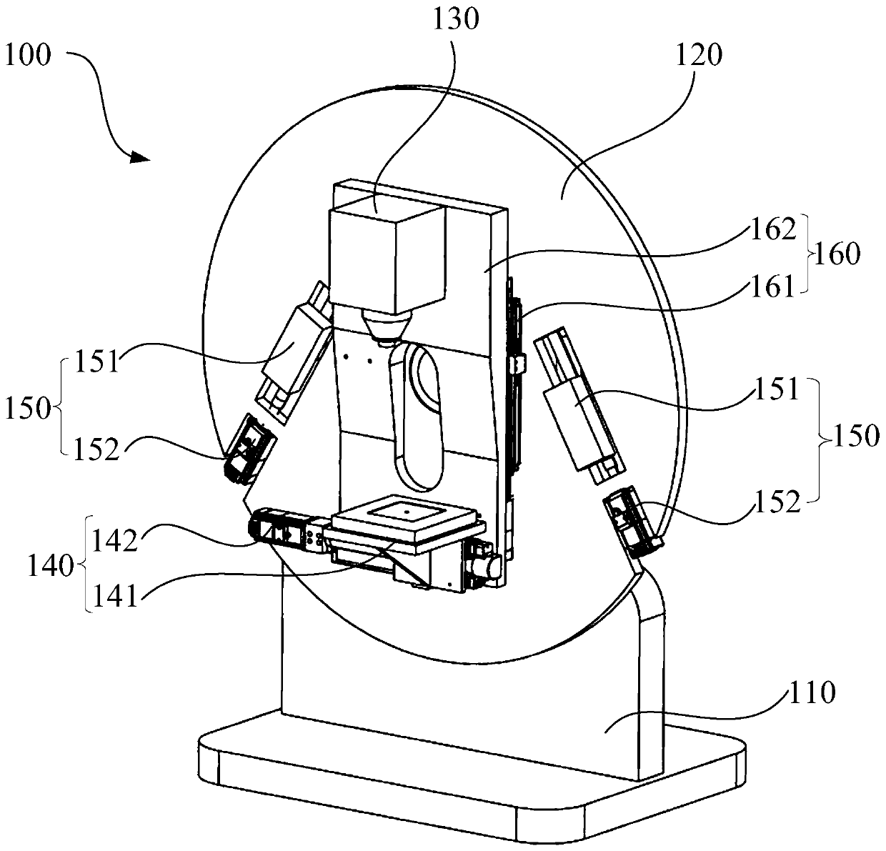
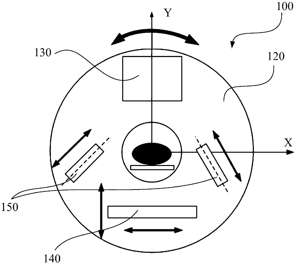
The invention provides an automatic balancing device, tomography equipment and an automatic balancing method. The automatic balancing device comprises a base, a rotary substrate, a ray emission assembly, a ray detection assembly and two counterweight assemblies, the rotary substrate has a radial direction and a tangential direction perpendicular to the radial direction, the ray emission assembly and the ray detection assemblies are oppositely installed on the rotary substrate in the radial direction, the ray detection assembly can move in the tangential direction, the two counterweight assemblies are symmetrically arranged on the rotary substrate with the radial direction as a symmetric line, and the counterweight assemblies are obliquely arranged relative to the radial direction. The detection assembly has a plurality of scanning view fields in the process of moving along the tangential direction, and a plurality of scanning view fields can be superposed and fused to obtain the overall image information of a scanned object so as to expand the scanning view field of the automatic balancing device and increase the imaging area of the scanned object.

Description

technical field [0001] The invention relates to the technical field of imaging equipment, in particular to an automatic balancing device, tomographic imaging equipment and an automatic balancing method. Background technique [0002] For the balance device in the current imaging equipment, the X-ray source and the X-ray detector can move radially to adjust the magnification, and automatically adjust the moving direction of the balance mass and the moving direction of the X-ray source and the X-ray detector parallel. The fixed balance mass adjusts the center of gravity of the rotating part to move to the x-axis. When the X-ray source and X-ray detector adjust the magnification ratio along the radial direction at the same time, the corresponding mobile balance mass will adjust the overall center of gravity. onto the y-axis. However, the scanning range of the above-mentioned balancing device is single, and the range of the obtained scanning image is narrow. Contents of the i...

Claims


Application Information

Patent Timeline
IPC IPC(8): A61B6/03
CPCA61B6/032A61B6/42A61B6/4266A61B6/4452
Inventor 梁宏锋林晓珍陈俊
Owner 武汉中科医疗科技工业技术研究院有限公司
Learn More