
Offshore wind power device applied to areas with abundant tidal energy

An offshore wind power and tidal energy technology, which is applied in the directions of wind power generation, wind turbine combination, installation/support of wind turbine configuration, etc. problem, to reduce the speed of ocean current erosion, increase the service life, and reduce the daily workload.

Active Publication Date: 2020-08-11
杭州翔毅科技有限公司
View PDF7 Cites 3 Cited by
  • Summary
  • Abstract
  • Description
  • Claims
  • Application Information

AI Technical Summary

Problems solved by technology

[0004] However, during the actual use of offshore wind power installations, technicians found that compared with the land environment, the offshore environment is much more complex. In addition to daily air erosion, sea water, tidal wave erosion and biological erosion also have a negative impact on wind power installations. Larger threats, technicians usually need to spend a lot of energy and cost on offshore wind power installations, especially tidal waves, the areas where offshore wind power installations are usually built are offshore areas, and sea level changes in these places will be affected by tides Larger, that is, the tidal wave will change the main washing position of the offshore wind power installation with the change of the tide. If the offshore wind power installation is fully protected, it will easily cause waste of resources and induce an increase in the cost of wind power generation. If the main parts of the wind power device are protected, it is very easy to cause excessive corrosion of parts of the offshore wind power device due to the excessive erosion of tidal waves, threatening the normal use of the offshore wind power device

Method used


Image

  • Offshore wind power device applied to areas with abundant tidal energy
  • Offshore wind power device applied to areas with abundant tidal energy
  • Offshore wind power device applied to areas with abundant tidal energy

Examples


Embodiment 1

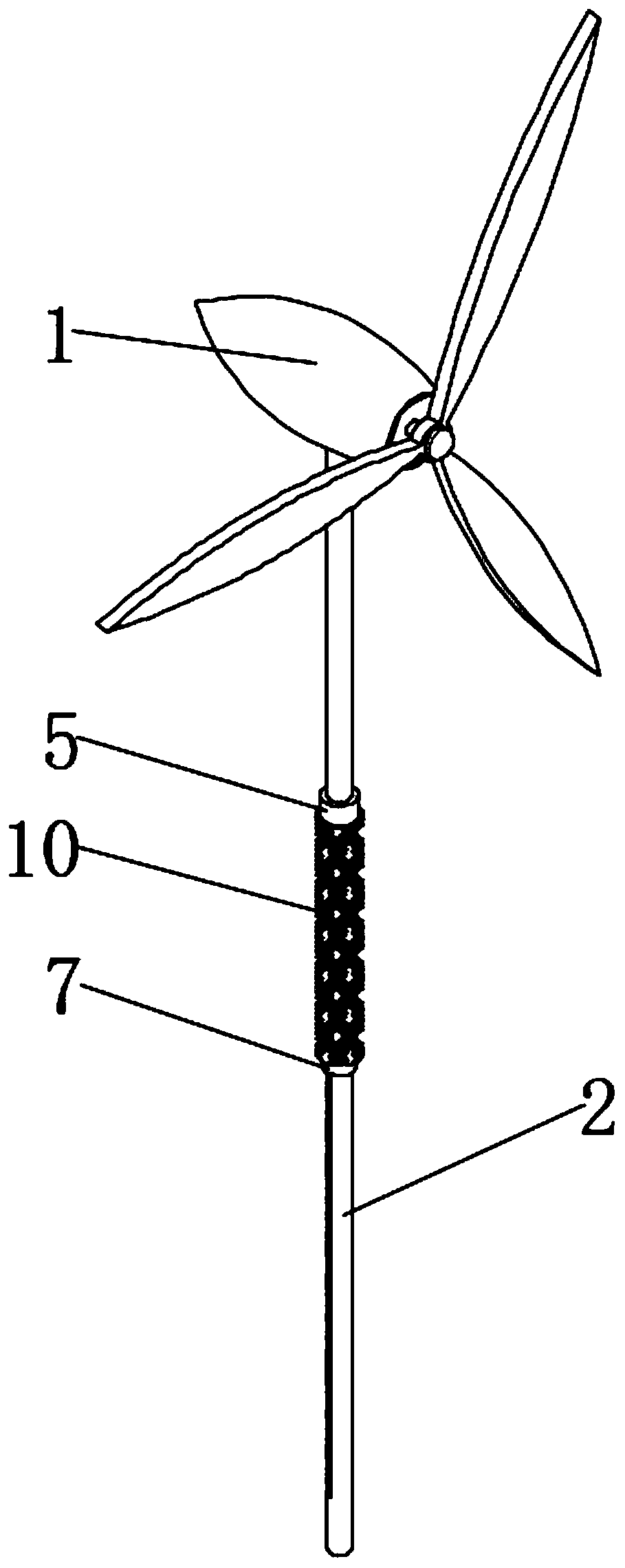
[0032] see Figure 1-5, an offshore wind power device applied to areas with abundant tidal energy, including a wind turbine 1, the lower end of the wind turbine 1 is fixedly connected to an anchor rod 2, and the wind turbine 1 is fixedly connected to the seabed through the anchor rod 2, and the wind turbine 1 The limit chute 3 is excavated on the side wall, and the outer side of the anchor rod 2 is sleeved with a suspension ring 5 and a counterweight 7 that match each other, and the suspension ring 5 is located on the upper side of the counterweight 7, and the suspension ring 5 and the counterweight The inner wall of the block 7 is respectively fixedly connected with a suspension slider 6 and a counterweight slider 8 that match the limit chute 3, and the anchor rod 2 and the suspension ring 5 pass through the limit chute 3 and the suspension slider 6 Sliding connection is realized, the sliding connection is realized between the anchor rod 2 and the counterweight 7 through the ...


PUM


Abstract

The invention discloses an offshore wind power device applied to areas with abundant tidal energy, and belongs to the field of offshore wind power devices. The offshore wind power device applied to the areas with the abundant tidal energy can realize that a protection device of the offshore wind power device can be changed along with ascending or descending of the tidal sea surface, the most comprehensive tide and sea wave erosion is completed with the minimum protection cost, the daily maintenance cost of the offshore wind power device is greatly reduced, and the daily workload of techniciansis reduced; and the erosion of sea waves to an anchoring rod body is greatly reduced through suspension rings, meanwhile, suspension of the suspension rings, balancing weights, wave-proof curtains and wave-proof fiber clusters is achieved through buoyancy of the suspension rings, scouring of the sea waves and ocean currents is effectively prevented with the minimum cost, the wave-proof curtains and the wave-proof fiber clusters simulate benthos of shallow sea, the ocean currents are divided to the maximum degree through the wave-proof fiber clusters, and the speed of ocean current erosion onan anchoring rod is greatly reduced.

Description

technical field [0001] The invention relates to the field of offshore wind power devices, and more specifically, relates to an offshore wind power device used in areas with abundant tidal energy. Background technique [0002] Wind power refers to converting the kinetic energy of wind into electrical energy. Wind is a kind of energy without pollution. Using wind power to generate electricity is very environmentally friendly and can generate huge amounts of electricity. Therefore, more and more countries pay more attention to wind power generation. However, the construction of traditional wind power related facilities is subject to environmental constraints. The most important thing is that the construction site needs a large area of ​​relatively flat terrain and abundant wind energy. Although it will affect the promotion of wind energy utilization to a certain extent, it will not hinder the overall promotion of wind energy generation. However, with the construction of wind po...

Claims


Application Information

Patent Timeline
Patent Type & Authority Applications(China)
IPC IPC(8): F03D9/25F03D13/25F03D80/00
CPCF03D9/25F03D13/25F03D80/00Y02E10/72Y02E10/727
Inventor 蒋经伟
Owner 杭州翔毅科技有限公司
Learn More