Seabed frame fixed type group anchor system

A fixed, frame technology, applied in anchor points, ship parts, transportation and packaging, etc., can solve the problems of poor installability, no new anchor type near islands and reefs, and high labor and material costs, so as to improve economy and efficiency. , Excellent engineering feasibility and good work reliability

Active Publication Date: 2020-08-11
CHINA SHIP SCIENTIFIC RESEARCH CENTER (THE 702 INSTITUTE OF CHINA SHIPBUILDING INDUSTRY CORPORATION)
View PDF12 Cites 2 Cited by
  • Summary
  • Abstract
  • Description
  • Claims
  • Application Information

AI Technical Summary

Problems solved by technology

[0003] Typical near-island reef coral facies geology is composed of calcareous coral sand on the upper layer and cemented reef limestone on the lower layer. There are cracks, collapses and caves in the shallow layer of the reef. The complex engineering geological characteristics have brought new challenges to the anchoring design of the floating platform. challenge
[0004] The traditional gravity anchoring foundation has the disadvantages of large configuration scale and large construction consumables, and the cost of manpower and material resources required for offshore installation is high. The anchoring capacity of typical anchor types in other types of marine engineering in reef seabed is relatively low Low, poor installability
[0005] With the development of technology and the improvement of engineering requirements, the design of new anchors suitable for topographic and geological conditions in sea areas near islands and reefs has become a trend of technological development. The submarine frame fixed group anchor designed based on the concept of embedded structure and multi-body group anchor system, with excellent performance and applicability, there is no similar design scheme of new anchor type near islands and reefs at home and abroad

Method used


Image

  • Seabed frame fixed type group anchor system
  • Seabed frame fixed type group anchor system
  • Seabed frame fixed type group anchor system

Examples


Embodiment Construction

[0029] The specific implementation manner of the present invention will be described below in conjunction with the accompanying drawings.

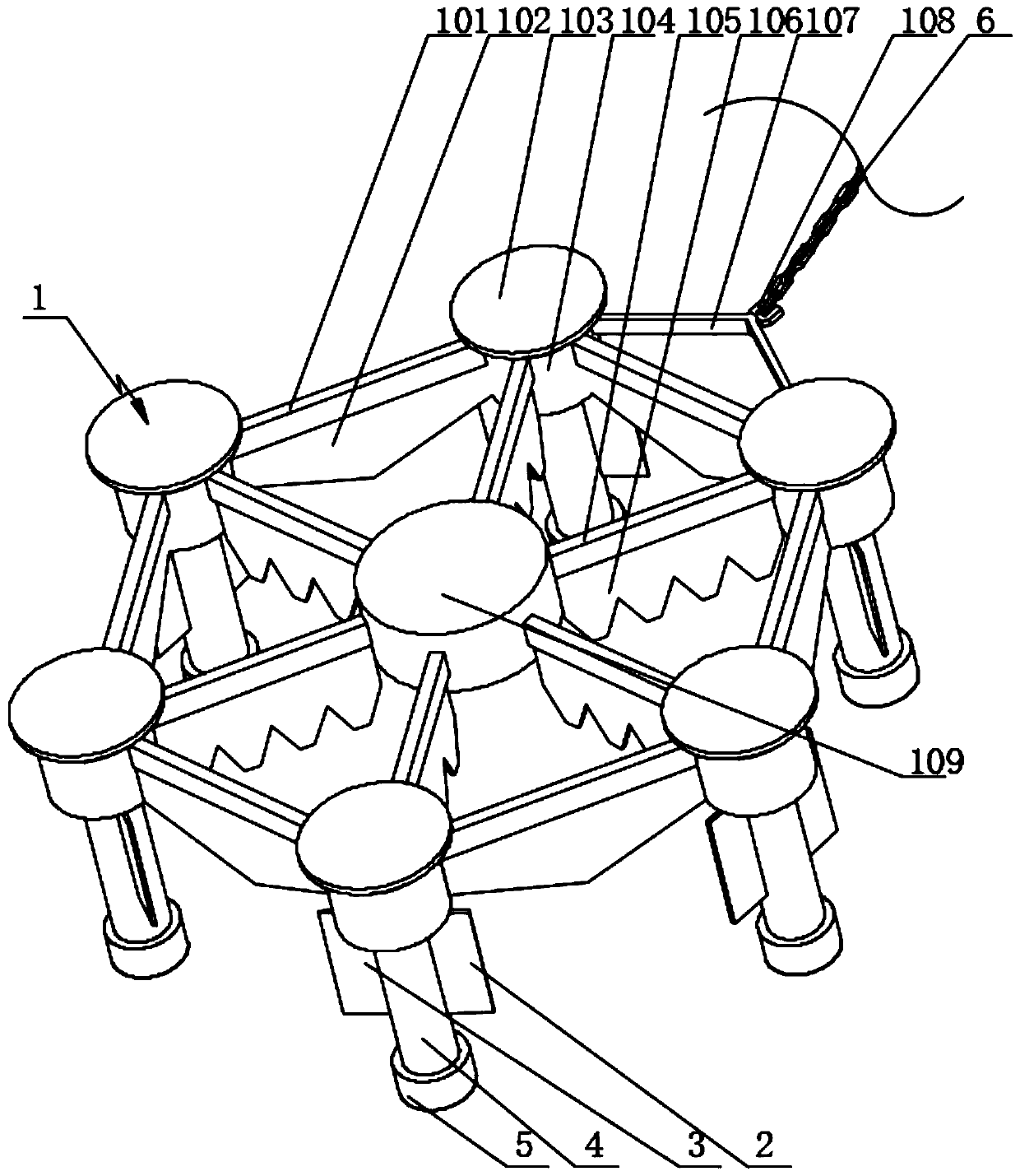
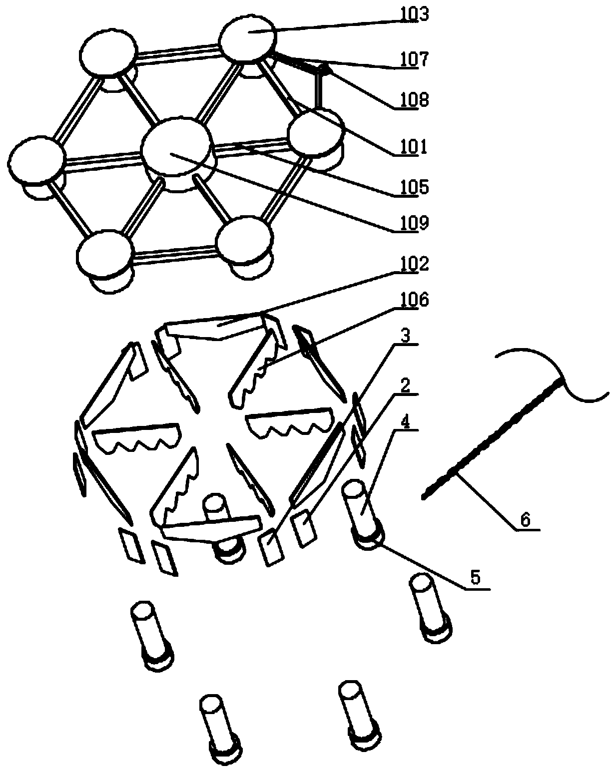
[0030] Such as figure 1 , figure 2 with image 3 As shown, the submarine frame fixed group anchor system of this embodiment includes an anchor frame assembly 1, the top of which is a hexagonal anchor structure, and a central short cylinder structure 109 is set in the middle, and the central short cylinder The outer circumference of the structure 109 is evenly spaced with six radial channel steels 105, the head of each radial channel steel 105 is connected to a hollow cylindrical shell 104, and the top of each hollow cylindrical shell 104 is equipped with an upper end cover 103 , two adjacent hollow cylindrical shells 104 are connected by external channel steel 101, and six external channel steel 101 are connected to form a hexagonal structure;

[0031] The bottom of each external channel steel 101 is equipped with a triangular plate 10...


PUM


Abstract

The invention relates to a seabed frame fixed type group anchor system. The system comprises an anchor frame assembly; the top of the anchor frame assembly is of a hexagonal anchor type structure; a central short cylinder structure is arranged in the middle of the anchor frame assembly; six pieces of radial channel steel are evenly arranged on the outer circumferential face of the center short cylinder structure at intervals; the head of each piece of radial channel steel is connected with a hollow cylinder shell; an upper end cover is installed at the top of each hollow cylinder shell; everytwo adjacent hollow cylinder shells are connected through external channel steel; and the six pieces of external channel steel are connected to form a hexagonal structure; a triangular plate is installed at the bottom of each piece of external channel steel; a damping plate is installed at the bottom of each piece of radial channel steel; a guide column is installed in each hollow cylindrical shell in a matched mode; a protective sleeve is installed at the bottom of each guide column; and a first thorn plate and a second thorn plate are symmetrically installed on the outer circumferential faceof each guide column. The work of the system is reliable .

Description

technical field [0001] The invention relates to the technical field of group anchor systems, in particular to a submarine frame fixed group anchor system. Background technique [0002] In recent years, in the development of marine and near-shore engineering, the anchoring and positioning technology of floating platforms under the topographic and geological conditions of the near-island reef sea area has become a difficult point in scientific research and engineering, among which the anchor type design suitable for coral facies reef topography and geology is extremely difficult . [0003] Typical near-island reef coral facies geology is composed of calcareous coral sand on the upper layer and cemented reef limestone on the lower layer. There are cracks, collapses and caves in the shallow layer of the reef. The complex engineering geological characteristics have brought new challenges to the anchoring design of the floating platform. challenge. [0004] The traditional gravi...

Claims


Application Information

Patent Timeline
Patent Type & Authority Applications(China)
IPC IPC(8): B63B21/26B63B21/34
CPCB63B21/26B63B21/34
Inventor 吴波程小明叶永林刘洪喜倪歆韵陈彧超许心愿
Owner CHINA SHIP SCIENTIFIC RESEARCH CENTER (THE 702 INSTITUTE OF CHINA SHIPBUILDING INDUSTRY CORPORATION)
Why Eureka
Try Eureka