Dual-purpose mechanical arm for intelligent manufacturing
A technology of intelligent manufacturing and manipulators, which is applied in the direction of manipulators, manufacturing tools, screwdrivers, etc., and can solve problems such as the inability to grasp and install screws
- Summary
- Abstract
- Description
- Claims
- Application Information
AI Technical Summary
Problems solved by technology
Method used
Image

Examples
Embodiment 1
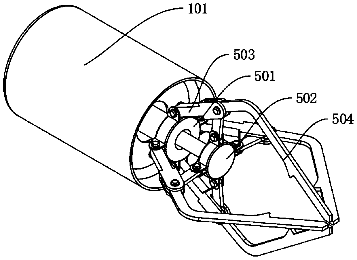
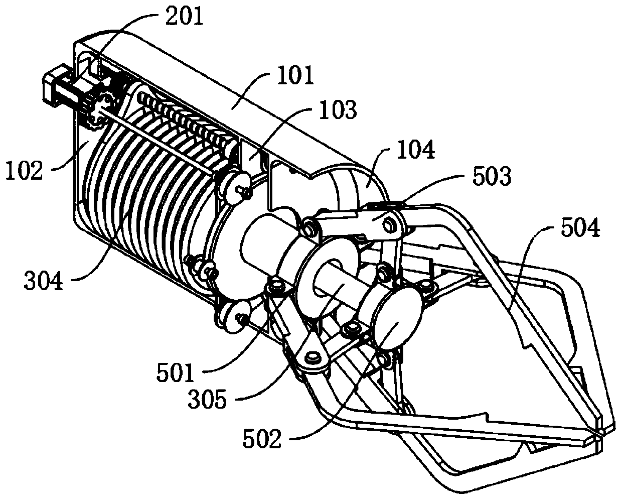
[0025] A dual-purpose manipulator for intelligent manufacturing, including: a main body shell 101, a driving bin 102, a linkage bin 103, and a rotating bin 104. The inside of the main body casing 101 is sequentially provided with a driving bin 102, a linkage bin 103, and a rotating bin. Bin 104, a driving mechanism is fixedly installed on the upper side of the driving bin 102, the right side of the driving mechanism is fixedly connected to the upper side of the linkage mechanism, the linkage mechanism is fixedly installed inside the linkage bin 103, and the middle part of the driving mechanism is meshed and connected with the intake drive mechanism. The air drive mechanism is fixedly installed inside the drive chamber 102, the middle part of the right end of the air intake drive mechanism is fixedly connected with the grasping mechanism, and the grasping mechanism is movably installed inside the rotating chamber 104.
[0026] The grabbing mechanism includes: a fixed chassis 501...
Embodiment 2
[0029] Embodiment 2: Based on Embodiment 1, the difference is:
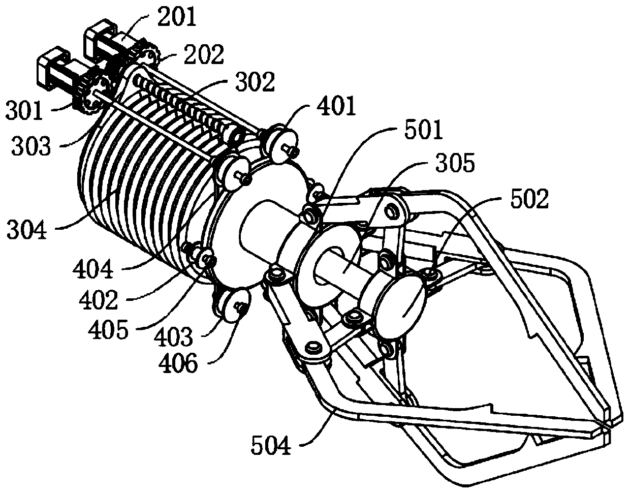
[0030] The driving mechanism includes: a servo motor 201 and a rotating ratchet 202. Two sets of servo motors 201 are fixedly installed on the upper left inside the drive chamber 102. The main shaft of the servo motor 201 is fixedly connected with the axis of the rotating ratchet 202 and the upper side of the linkage mechanism from left to right. The rotating ratchet 202 is engaged with the intake drive mechanism above the inner side.
[0031] The intake driving mechanism includes: transmission gear 301, transmission screw rod 302, moving ring 303, compressed air bag 304 and telescopic connecting pipe 305, the inner side of the rotating ratchet 202 is meshed with the front and rear sides of the transmission gear 301, and the axis of the transmission gear 301 It is fixedly connected with the left end of the transmission screw rod 302, and the right end of the transmission screw rod 302 is movably connected with th...
Embodiment 3
[0033] Embodiment 3: Based on Embodiment 1 and 2, but the difference is:
[0034] The linkage mechanism includes: a rotating wheel 401, a limit wheel 402, a transmission wheel 403, a transmission wheel set 404, a limit shaft 405, a transmission shaft 406 and a rotating ring 407, and the right side of the main shaft of the servo motor 201 is in turn aligned with the axis of the upper end of the drive wheel set 404. It is fixedly connected with the shaft center of the rotating wheel 401, the shaft center of the lower end of the transmission wheel set 404 is fixedly connected with the left side of the transmission shaft 406, the middle part of the transmission shaft 406 is fixedly connected with the shaft center of the transmission wheel 403, and the left and right ends of the transmission shaft 406 are movable with the inner wall of the linkage warehouse 103 Connection, the rotating wheel 401 and the transmission wheel 403 are flexibly connected with the four corners on the upper...
PUM
 Abstract
Description
Claims
Application Information
 - R&D
- Intellectual Property
- Life Sciences
- Materials
- Tech Scout
- Unparalleled Data Quality
- Higher Quality Content
- 60% Fewer Hallucinations
Browse by: Latest US Patents, China's latest patents, Technical Efficacy Thesaurus, Application Domain, Technology Topic, Popular Technical Reports.
© 2025 PatSnap. All rights reserved.Legal|Privacy policy|Modern Slavery Act Transparency Statement|Sitemap|About US| Contact US: help@patsnap.com