Eureka AIR delivers breakthrough ideas for toughest innovation challenges, trusted by R&D personnel around the world.

Ratchet pruner with dual pivot lubrication bolts

a technology of lubrication bolts and ratchets, which is applied in the field of ratchet pruning shears, can solve the problems of deformation of the holes in the handle, difficult change, and inability to precisely reciprocate the pruning shear, and achieve the effect of lubricating the pivoting members and reducing the friction between the members

Inactive Publication Date: 2007-04-12
BARNEL INT
View PDF17 Cites 37 Cited by
  • Summary
  • Abstract
  • Description
  • Claims
  • Application Information

AI Technical Summary

Benefits of technology

[0006] In accordance with the invention, a pruner having a ratchet system includes dual lubricating pivot bolts for connection of the pivoting portions of the pruner. The pivot bolt is provided with a lubricant cell with plural channels to distribute the lubricant to the mating areas of the pivoting members in the area of the pivot point, to effectively lubricate the pivoting members, thereby resulting in reduction in friction between the members. A lubricant receiving well is provided at the lubricant receiving position, for ease of re-supply of lubricant.
[0008] It is a further object of the present invention to provide an improved pruner using dual pivot point nut members with improved lubricant delivery and re-supply features thus promoting less tool wear and overall longevity.
[0010] It is a further object of the present invention to provide an improved pruner with extensible handles having an improved locking mechanism for the extensible handles.

Problems solved by technology

However, such configuration can lead to imprecise reciprocating motion of the pruner.
The cylinder / round hole results in a single point (tangent) application of force which can result in deformation of the holes in the handle, since typically users will slide the handles when adjusting the length, allowing the cylindrical lock to find the hole and snap into place with the extension (or retraction) handle length force being applied at the same time.
Over time it may be necessary to replace the spring, but the typical configuration of the spring makes changing it difficult.
There may be a tendency for the anvil to cause the blade to become dull more quickly, since the metal of the blade and anvil will meet when the pruner is fully closed.

Method used


Image

  • Ratchet pruner with dual pivot lubrication bolts
  • Ratchet pruner with dual pivot lubrication bolts
  • Ratchet pruner with dual pivot lubrication bolts

Examples


Embodiment Construction

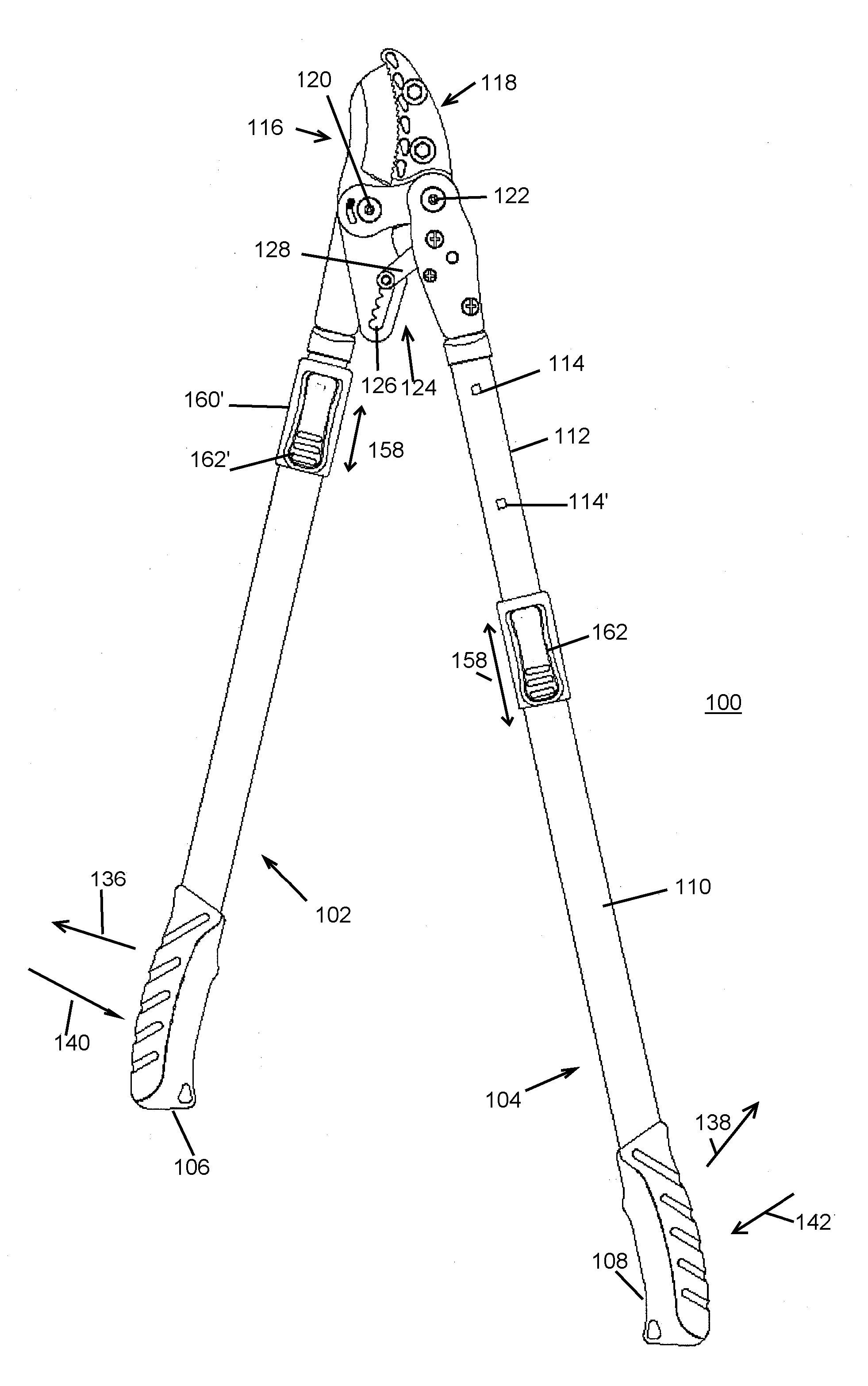
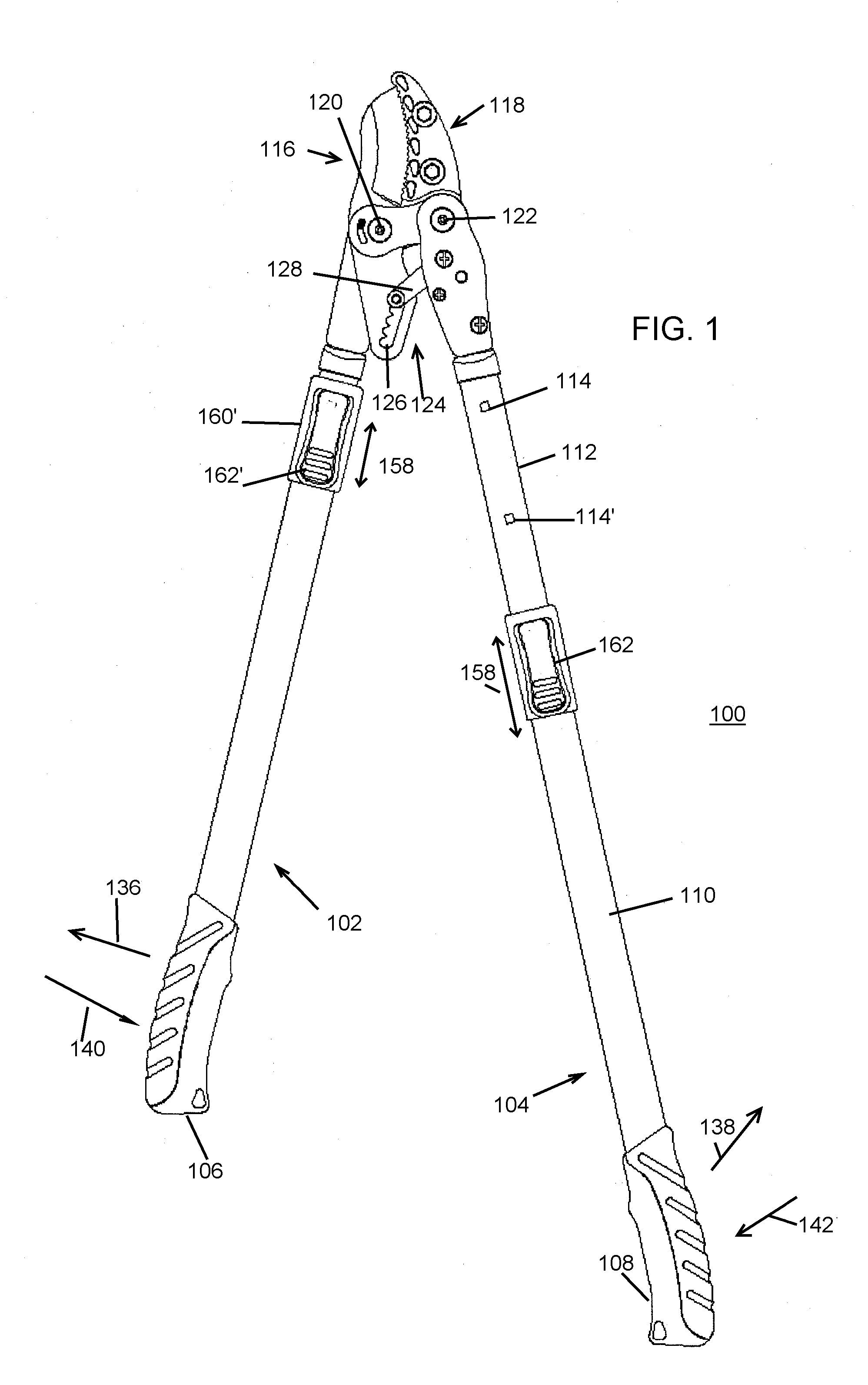
[0026]FIG. 1 is a view of a ratchet pruner in accordance with the present invention. The pruner 100 employs first and second extensible handles 102, 104 which carry ergonomic grips 106, 108 thereon. The grips are suitable TPR or other rubber or rubber like material that promotes comfort, reduced stress, supports ergonomic concepts and is resistant to UV light, oil, water and other environmental factors. Handle 104 comprises a first outer telescoping tubular portion 110 and a tubular portion 112 received in telescoping fashion within the interior of portion 110. Plural square depressions or openings 114, 114 are formed in the portion 112, suitably spaced at certain intervals along the extent of portion 112. Two such openings 114 are visible in FIG. 1, but it will be understood that corresponding additional openings 114 are formed along the extent of portion 112.

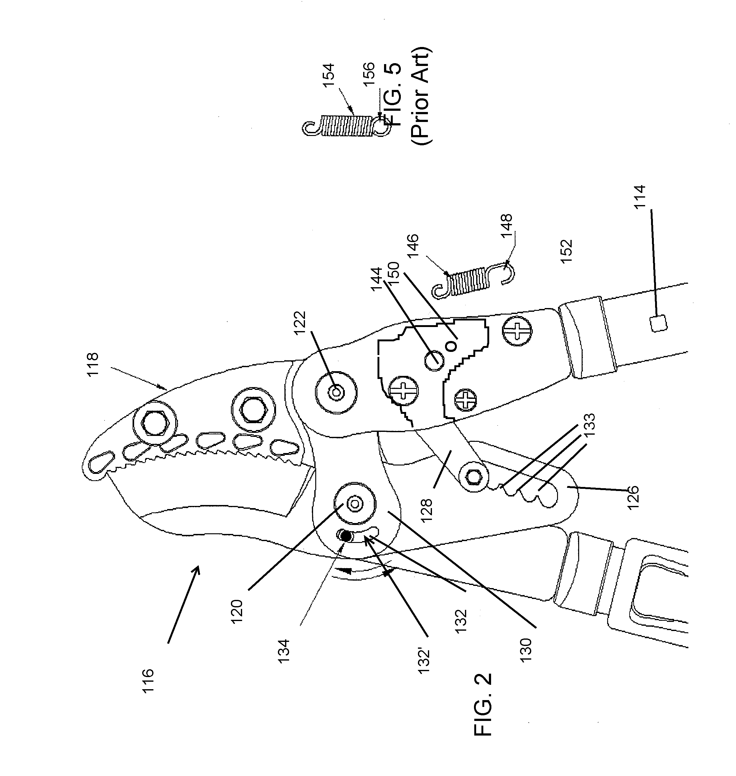
[0027] The handles 102, 104, connect to the pruner blade jaw portions 116 and 118, which employ pivot portions 120 and 122,...


PUM


Abstract

A pruner employs dual lubricating fasteners as pivots. Each pivot has a head, and a shank which is provided with a lubricant cell and plural channels. The lubricant cell is in communication with the exterior of the shank area, the channels enabling the lubricant contained in the lubricant cell to lubricant the two blades. The lubricant cell includes a depressed oiling region for containing oil therein during re-lubrication. The shank has outer threads to mesh with inner threads of the nut. An anvil portion is provided in a material less likely to dull the blade portion. Extensible handles are providing, having lock member with square or rectangular lock iron for improved operation. A ratchet spring configuration provides ease of replacement of the spring.

Description

BACKGROUND OF THE INVENTION [0001] This invention relates to pruning shears, and more particularly to a ratchet pruning shear employing dual pivot lubrication bolts. [0002] Pruning shears employing ratchet mechanisms enable easier cutting of branches than would be possible with non-ratchet type pruners. The user is able to cut partially through a branch, the ratchet mechanism locks onto the branch while the user is able to re-open the handles of the pruner to close down further on the branch. Thus multiple actuations of the handles of the pruner may be employed to cut a single branch while requiring less exertion by the user at any individual actuation. [0003] Having extensible handles on a pruner can be desirable, enabling adjustment of the overall length of the pruner and its reach, depending on the particular use or user. The conventional mechanism for allowing the extension employs a circular hole in a stationary portion of the handle tube, and that portion of the handle tube fi...

Claims


Application Information

Patent Timeline
IPC IPC(8): B26B13/28B25F3/00
CPCB25G1/04A01G3/0251
Inventor NELSON, LINN E.ZELLER, KARL H.WONG, SOON KIM
Owner BARNEL INT
Why Eureka
Eureka Blog
Learn More