Eureka AIR delivers breakthrough ideas for toughest innovation challenges, trusted by R&D personnel around the world.

Robot power joint with turbulent flow heat dissipation structure and robot

A technology of heat dissipation structure and joints, applied in the field of robots, can solve the problems of complex structure of heat dissipation device, incompatibility with the lightweight, compact, and large size of bionic robots, so as to enhance the convective heat dissipation capability, reduce the transient temperature rise, increase the The effect of heat dissipation area

Inactive Publication Date: 2020-08-07
BEIJING INSTITUTE OF TECHNOLOGYGY
View PDF5 Cites 0 Cited by
  • Summary
  • Abstract
  • Description
  • Claims
  • Application Information

AI Technical Summary

Problems solved by technology

Although liquid cooling, oil cooling or adding a cooling fan can meet the heat dissipation needs of the motor, their volume is large and the structure of the heat dissipation device is complex, which does not meet the requirements of lightweight and compact bionic robots

Method used


Image

  • Robot power joint with turbulent flow heat dissipation structure and robot
  • Robot power joint with turbulent flow heat dissipation structure and robot
  • Robot power joint with turbulent flow heat dissipation structure and robot

Examples


Embodiment Construction

[0032] In order to make the purpose, technical solutions and advantages of the embodiments of the present invention more clear, the embodiments of the present invention will be further described in detail below in conjunction with the accompanying drawings. Here, the exemplary embodiments and descriptions of the present invention are used to explain the present invention, but not to limit the present invention.

[0033] Here, it should be noted that, in order to avoid obscuring the present invention due to unnecessary details, only the structures and / or processing steps that are closely related to the solution according to the present invention are shown in the drawings, while those related to the present invention are omitted. Invent other details that don't really matter.

[0034] It should be emphasized that the term "comprises / comprises / has" when used herein refers to the presence of a feature, element, step or component, but does not exclude the presence or addition of on...


PUM


Abstract

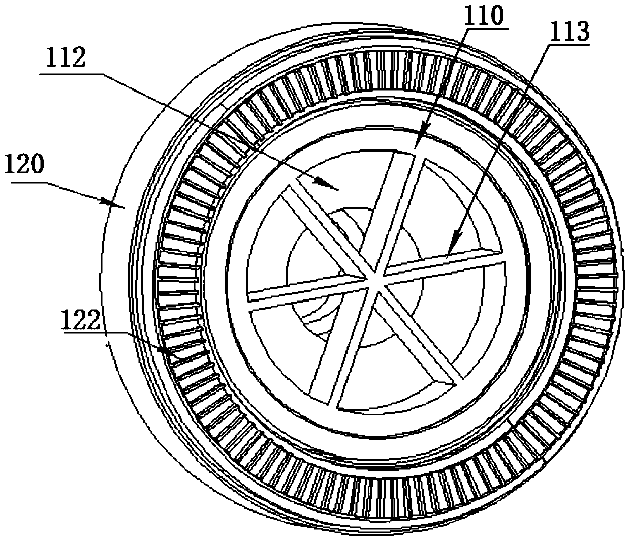
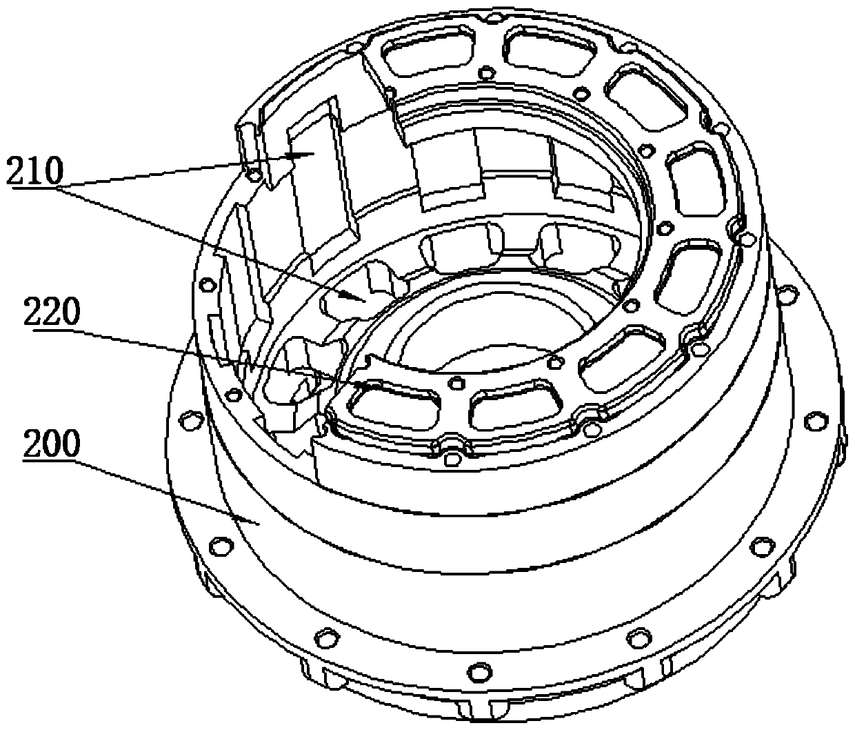
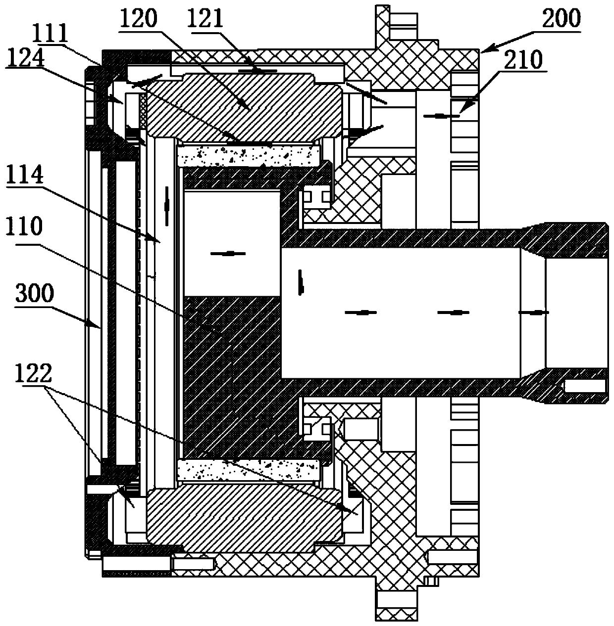
The invention provides a robot power joint with a turbulent flow heat dissipation structure and a robot. The power joint comprises a motor, a joint shell and an end packaging part, the motor is installed in a hollow cavity formed by the joint shell, the end packaging part is located at the end of the motor, a first gap is formed between a rotor and a stator, and a first end gap is formed between afirst end of the rotor and the end packaging part; a plurality of axial airflow channels are formed in the middle of the rotor through spacers; a second gap is formed between the circumferential surface of the stator and the joint shell, a second end gap is formed between the first end of the stator and the end packaging part, and the first end of the stator and the first end of the rotor are thesame end of the motor; the axial airflow channels, the first end gap and the first gap form a communicated first air duct; an axial airflow air duct, the second end gap and the second gap form a communicated second air duct; one end, far away from the first end gap, of the joint shell is provided with a heat dissipation flow channel for communicating the first air duct and the second air duct with the outside.

Description

technical field [0001] The invention relates to the technical field of robots, in particular to a robot power joint and a robot with a spoiler cooling structure. Background technique [0002] The overall humanoid robot has the requirements of light weight, high strength, high explosion, high reliability, etc.; as the power source of the robot, the power joint requires that the torque motor as the core power component must have a high peak torque density, that is, the motor unit weight must output highest possible torque. However, in the state of continuous rotation of the motor rotor, the iron core of the motor will generate iron loss in the alternating magnetic field, copper loss will also occur after the winding is energized, and other types of losses will also occur, which will cause the temperature of the motor to rise . When the temperature rise of the motor exceeds the maximum operating temperature, the motor will be damaged, thereby destroying the stability of the d...

Claims


Application Information

Patent Timeline
IPC IPC(8): H02K9/06H02K1/32H02K9/22B25J17/00B25J19/00
CPCB25J17/00B25J19/0054H02K1/32H02K9/06H02K9/22
Inventor 黄强张武孟非孟兆平余张国曲道奎
Owner BEIJING INSTITUTE OF TECHNOLOGYGY
Why Eureka
Eureka Blog
Learn More