High-stability permanent magnet synchronous motor driven by single inverter
A permanent magnet synchronous motor, high-stability technology, applied in the direction of electromechanical devices, electrical components, electric components, etc., can solve the problems of unbalanced moment of inertia, unstable motor operation, etc., to improve the vibration reduction effect, reduce damage, The effect of improving the effect of vibration reduction
- Summary
- Abstract
- Description
- Claims
- Application Information
AI Technical Summary
Problems solved by technology
Method used
Image


Examples
Embodiment 1
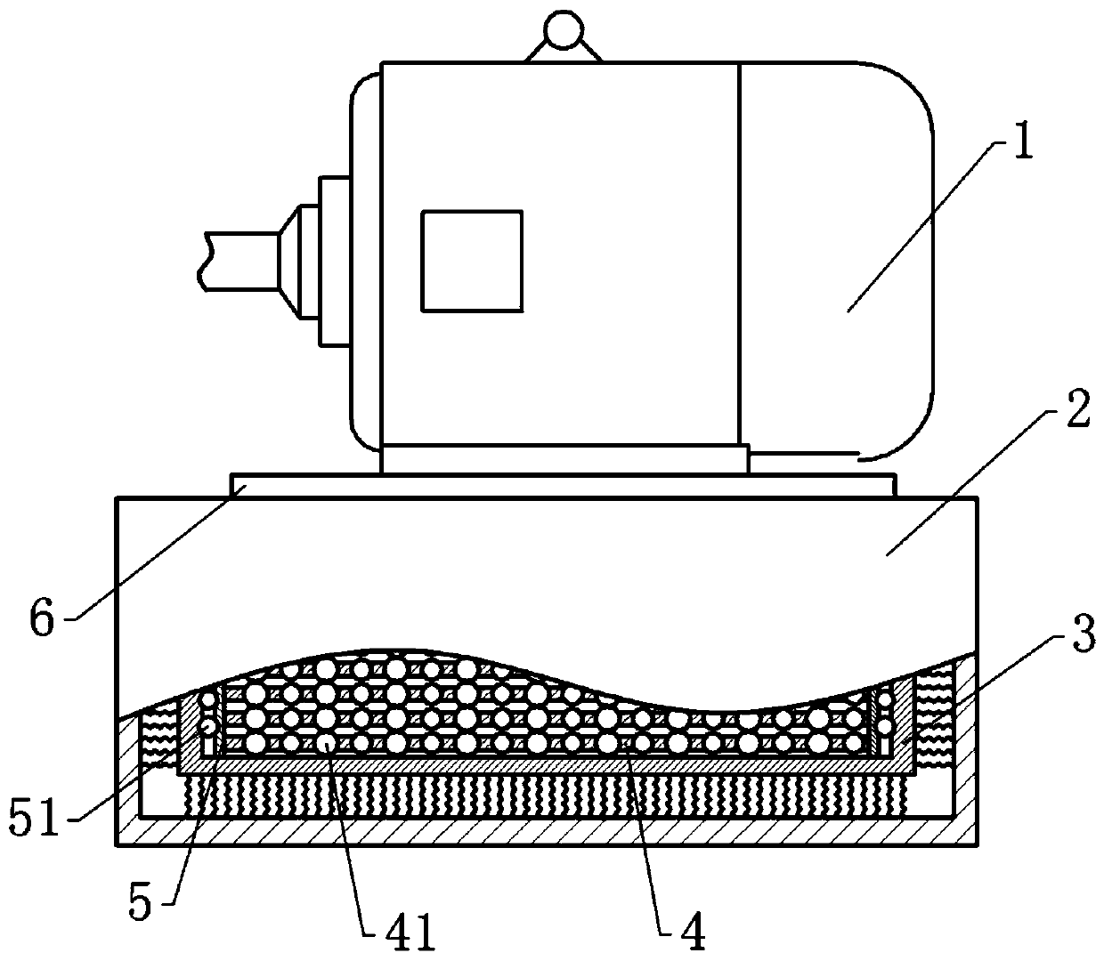
[0038] A high-stability permanent magnet synchronous motor driven by a single inverter, basically as attached figure 1 As shown, the mounting base 2 and the motor body 1. The motor main body 1 includes a rotor 11, a stator 12 and a casing 13 ( figure 1 Not shown in ), the drive shaft 14 is connected to the stator 12 for coaxial rotation, and the rotor 11 is wrapped on the outside of the drive shaft 14 . The left end of the driving shaft 14 passes through the casing 13 and extends out of the casing 13 , and the left end of the driving shaft 14 is rotatably connected with the casing 13 . It also includes a connecting plate 6 screwed to the bottom of the housing 13 .
[0039] Mounting seat 2 is provided with a mounting groove, and a limiting frame 3 is arranged in the mounting groove, and a spring or a limiting member is arranged between the bottom and side walls of the limiting frame 3 and the mounting groove, preferably a spring in this embodiment. A damping assembly is arra...
Embodiment 2
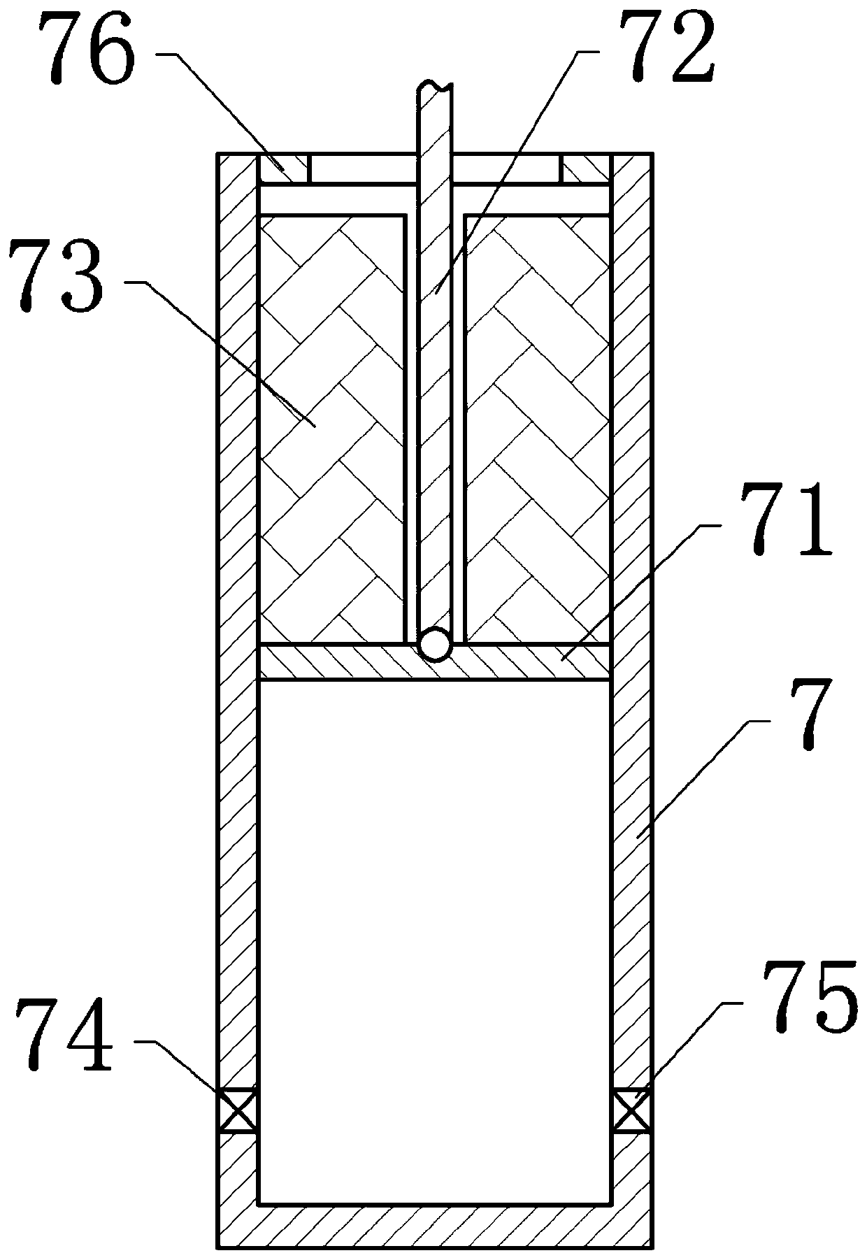
[0048] Embodiment 2 differs from Embodiment 1 only in that, as figure 2 As shown, in this embodiment, a limiting member is provided between the limiting frame 3 and the bottom and side walls of the installation groove, and no spring is provided. Take the limiter at the bottom as an example, the limiter includes a sliding barrel 7 welded on the mounting groove, the top of the sliding barrel 7 is open, and a limit ring 76 is arranged on the inner wall of the top of the sliding barrel 7 . A slide plate 71 is vertically slidably connected in the sliding bucket 7 , and a pull rod 72 is hinged on the top of the slide plate 71 , and the top of the pull rod 72 is hinged to the bottom of the limit frame 3 .
[0049] The slide barrel 7 is provided with an air inlet 74 and an air outlet 75 at the place below the slide plate 71, and an air intake check valve is provided in the air inlet 74. When the slide plate 71 slides upwards, the pressure at the bottom of the slide barrel 7 decreases...
Embodiment 3
[0053] Embodiment 3 differs from Embodiment 2 only in that, as image 3 As shown, a cooling channel 121 is also provided in the stator 12. The cooling channel 121 is spirally arranged along the axial direction of the stator 12. The left end of the cooling channel 121 is an air intake end, and the right end of the cooling channel 121 is an air outlet end. combine Figure 4 As shown, the left end of the stator 12 is further provided with an annular groove 122 wrapping the cooling channel 121 , and the stator 12 is also provided with a guide hole connecting the annular groove 122 with the cooling channel 121 . Three cooling fins 141 are arranged on the part of the left end of the driving shaft 14 inside the housing 13 . The cooling fins 141 are spliced into the shape of fan blades and can lead the external air into the cooling channel 121 . Vent holes 131 are provided on both left and right ends of the shell 13 . The air outlet 75 of the sliding barrel 7 is also connected wit...
PUM
 Abstract
Description
Claims
Application Information
 - R&D
- Intellectual Property
- Life Sciences
- Materials
- Tech Scout
- Unparalleled Data Quality
- Higher Quality Content
- 60% Fewer Hallucinations
Browse by: Latest US Patents, China's latest patents, Technical Efficacy Thesaurus, Application Domain, Technology Topic, Popular Technical Reports.
© 2025 PatSnap. All rights reserved.Legal|Privacy policy|Modern Slavery Act Transparency Statement|Sitemap|About US| Contact US: help@patsnap.com