Wireless charging receiving end, terminal and wireless charging method

A wireless charging and receiving end technology, applied in battery circuit devices, current collectors, electric vehicles, etc., can solve the problems of inability to guarantee the output voltage reliability of the receiving end, slow response speed of current control, charging stop, etc., to improve user experience and Charging safety, ensuring reliability and stability, and improving the effect of current accuracy

Pending Publication Date: 2020-08-07
BEIJING XIAOMI MOBILE SOFTWARE CO LTD
View PDF0 Cites 5 Cited by
  • Summary
  • Abstract
  • Description
  • Claims
  • Application Information

AI Technical Summary

Problems solved by technology

However, this voltage regulation method needs to be intervened by software, not only cannot guarantee the reliability of the output voltage of the receiving end, but also the response speed of the current control is very slow
In addition, it is easy to be interfered by scenarios such as sudden load changes of the terminal system and changes in the position of the terminal on the charging board, making the entire wireless charging system unstable and even causing charging to stop, resulting in poor user experience and hidden dangers to charging safety.

Method used


Image

  • Wireless charging receiving end, terminal and wireless charging method
  • Wireless charging receiving end, terminal and wireless charging method
  • Wireless charging receiving end, terminal and wireless charging method

Examples


Embodiment Construction

[0083] Reference will now be made in detail to the exemplary embodiments, examples of which are illustrated in the accompanying drawings. When the following description refers to the accompanying drawings, the same numerals in different drawings refer to the same or similar elements unless otherwise indicated. The implementations described in the following exemplary examples do not represent all implementations consistent with the present disclosure. Rather, they are merely examples of apparatuses and methods consistent with aspects of the present disclosure as recited in the appended claims.

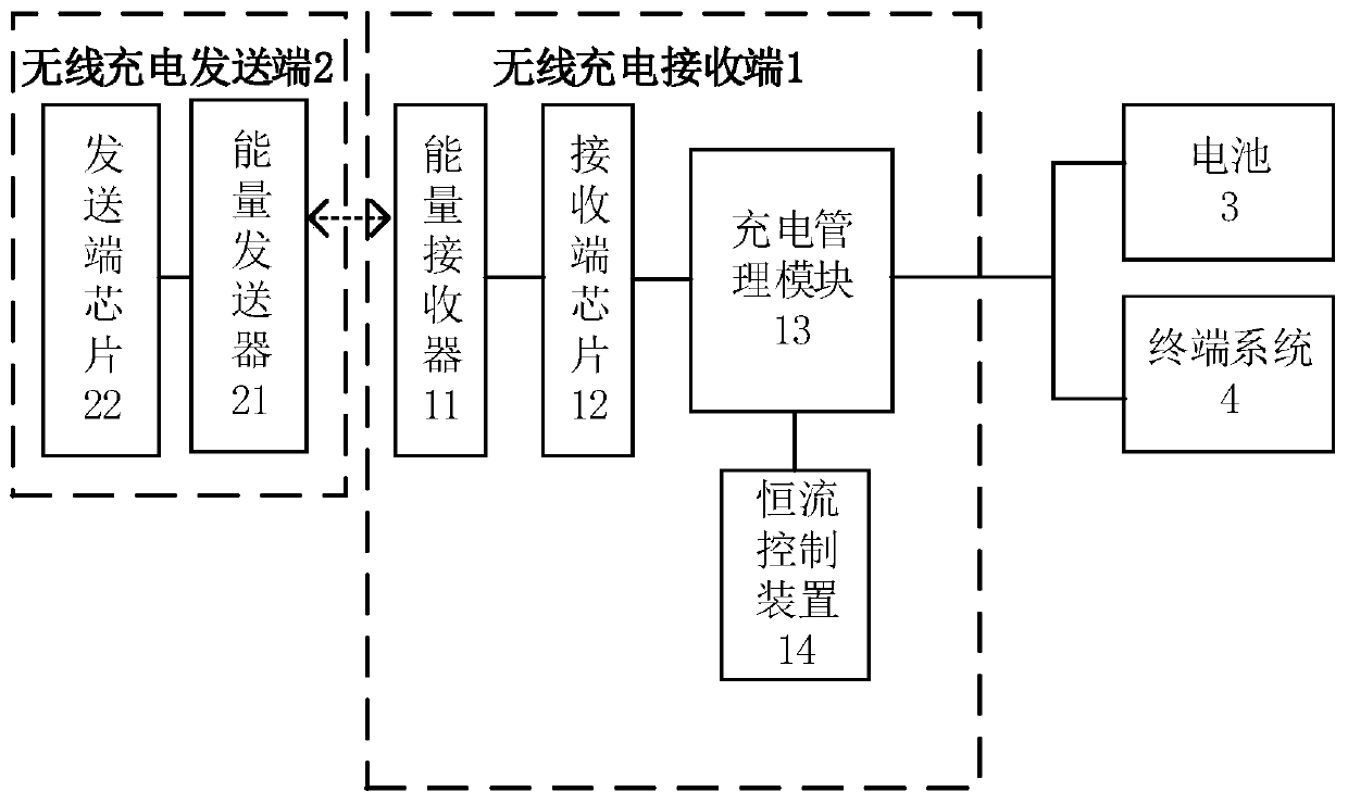
[0084] figure 2 It is a block diagram of a wireless charging system shown according to an exemplary embodiment. refer to figure 2 , the wireless charging system may include: a wireless charging receiving end 1 and a wireless charging sending end 2 .

[0085] Such as figure 2 As shown, the above wireless charging transmitter 2 may include an energy transmitter 21 and a transmitte...


PUM


Abstract

The invention relates to a wireless charging receiving end, a terminal and a wireless charging method. The wireless charging receiving end comprises an energy receiver, a receiving end chip, a charging management module and a constant current control device, wherein the receiving end chip converts alternating current into direct current and modulates and demodulates a wireless signal, the chargingmanagement module outputs the output current and the target current of the charging management module to the constant current control device, and in the constant current charging stage, the constantcurrent control device adjusts the output voltage of the charging management module according to the output current and the target current, so that the charging management module performs constant current output according to the target current. According to the invention, the reliability and stability of the output voltage of the wireless charging receiving end can be ensured, and the response speed of current control is high; the stepping of voltage regulation can reach 20 mV, and the current precision is improved; and the whole charging process is stable and is not influenced by load fluctuation of the terminal system, so that the user experience and the charging safety are improved.

Description

technical field [0001] The present disclosure relates to the technical field of charging, and in particular to a wireless charging receiving end, a terminal and a wireless charging method. Background technique [0002] At present, many terminal manufacturers have begun to use high-voltage direct charging to improve charging efficiency and charging current, that is, using a 1 / 2 voltage divider switched capacitor converter for charging. This method can be applied to wired charging and wireless charging. Such as figure 1 As shown, most of the current wireless charging receivers use BUCK, LDO or other step-down converters plus external circuits (ie figure 1 The constant voltage control circuit shown in ) or the internal control circuit of the chip itself to adjust the output voltage of the receiving end, so as to achieve the purpose of adjusting the charging current into the battery. The step of voltage adjustment is generally 200mV. However, this voltage regulation method nee...

Claims


Application Information

Patent Timeline
Patent Type & Authority Applications(China)
IPC IPC(8): H02J7/02H02J7/04H02J50/80
CPCH02J7/04H02J50/80
Inventor 马强
Owner BEIJING XIAOMI MOBILE SOFTWARE CO LTD
Why Eureka
Try Eureka