Optical photographing celestial body measurement telescope system with three pointing single focal planes

An optical photography and astrometric technology, applied in telescopes, optics, optical components, etc., can solve the problem of not being able to determine a full set of earth orientation parameters and only observing a single star.

Active Publication Date: 2020-08-07
SHANGHAI ASTRONOMICAL OBSERVATORY CHINESE ACAD OF SCI
View PDF4 Cites 0 Cited by
  • Summary
  • Abstract
  • Description
  • Claims
  • Application Information

AI Technical Summary

Problems solved by technology

[0003] Purpose of the invention: the purpose of the present invention is to address the deficiencies in the prior art, to provide a three-pointing single focal plane optical photographic astrometric telescope system, to overcome the need for large-scale station deployment and the need for artificial Issues with adjusting levels, observing only one star at a time, and not being able to determine the full set of Earth orientation parameters

Method used


Image

  • Optical photographing celestial body measurement telescope system with three pointing single focal planes
  • Optical photographing celestial body measurement telescope system with three pointing single focal planes
  • Optical photographing celestial body measurement telescope system with three pointing single focal planes

Examples


Embodiment

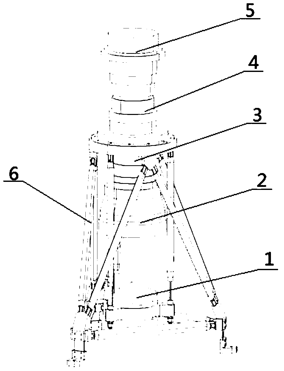
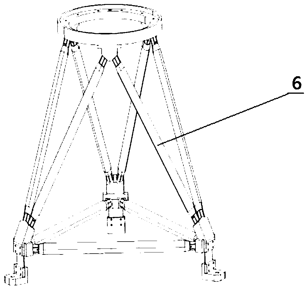
[0027] Embodiment: A three-point single focal plane optical photographic astrometric telescope system, including a telescope body part and a support part.

[0028] 1. The main part of the telescope

[0029] 1. Optical design

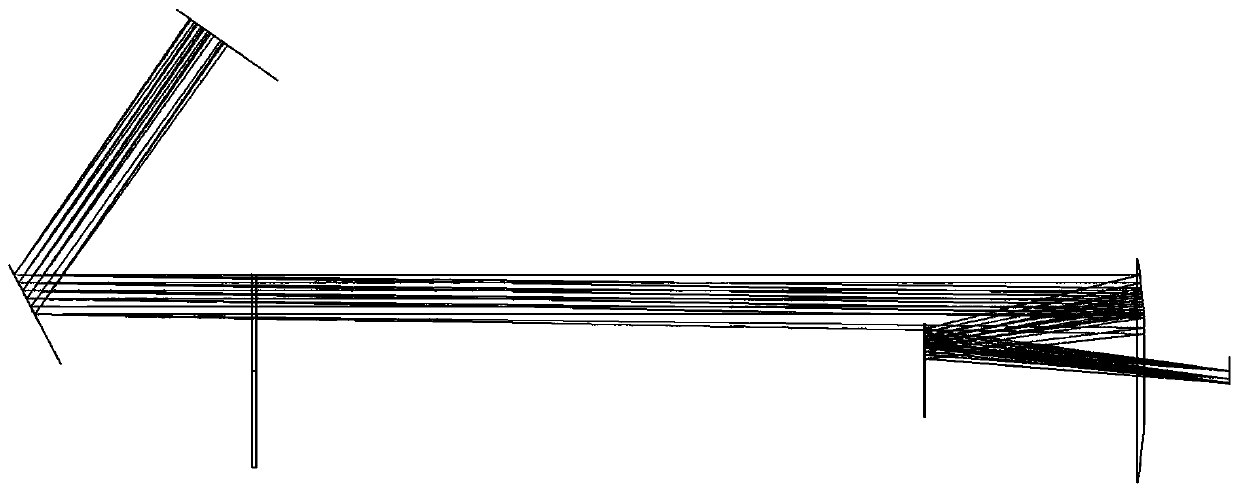
[0030] A whole piece of crystallized glass is ground into a tetrahedron with three reflecting surfaces as the reflecting mirror, and the angle between each reflecting surface is 135 degrees. Grind a set of refracting mirrors with glass-ceramics, the aperture is 25 cm, and the internal optical path design of the single-tube three-pointing telescope figure 2 , The plan is to use the Schmitt-Cassegrain improved telescope optical system, this plan has the advantages: the primary and secondary mirrors are spherical, processing and testing technology is mature; the image surface is located behind the primary mirror, easy to install and focus; the entire mirror Only one correcting mirror is needed in the tube, which makes the optical system simpler and more compact ...


PUM


Abstract

The invention discloses an optical photographing celestial body measurement telescope system with three pointing single focal planes. The system comprises a telescope main body part and a bracket part, wherein a reflector, a correction mirror, a secondary mirror, a primary mirror and an image acquisition camera are sequentially arranged on a light path of the telescope main body part; the reflector is a prism with three reflecting surfaces, the included angle between every two of the three reflecting surfaces is 135 degrees, and reflected light on the three reflecting surfaces of the reflectorenters the lens cone in parallel and is perpendicular to the correction lens. The three-directional single-focal-plane optical photographing celestial body measurement telescope is equivalent to observation of three independent stations which are 120 degrees away from each other in the world; meanwhile, the measurement of the earth polar shift and rotation parameters UT1 (or day length LOD) can be realized only by observing for several hours, the actual measurement and change sequence of all earth orientation parameters can be continuously provided after long-term (several months) continuousobservation, and the earth attitude parameters can be independently and autonomously provided for a user by a single set of equipment.

Description

Technical field [0001] The invention belongs to the technical field of astronomical optical photographic astrometry, and particularly relates to an optical photographic astronomical telescope for determining the orientation parameters of the earth. Background technique [0002] At present, various astronomical geodesy techniques used to determine the orientation parameters of the earth (that is, precession, nutation, pole shift and rotation) require observation of celestial bodies in different celestial regions at large-span stations on the earth to determine the orientation parameters of the earth. In the past, the more classic instruments (such as contour gauge, zenith tube, meridian ring, and midplane) need to be deployed on a large scale, requiring precise manual adjustment to construct a clear geometric relationship with the local plumb line and the station horizontal plane. Usually It can only provide results with a time resolution of 5 days (the earth orientation parameter...

Claims


Application Information

Patent Timeline
IPC IPC(8): G02B23/02G02B23/16
CPCG02B23/02G02B23/16
Inventor 齐朝祥赵铭于涌杨德华唐正宏黄乘利孙中苗曾安敏
Owner SHANGHAI ASTRONOMICAL OBSERVATORY CHINESE ACAD OF SCI
Why Eureka
Try Eureka