A power cable snow sweeper and control system
A power cable and cleaning machine technology, which is applied to the installation of cables, overhead lines/cable equipment, electrical components, etc., can solve the problems of cable cleaning, practical limitations, and inability to realize remote control, etc., to achieve high cleaning efficiency, Strong stability and good effect
- Summary
- Abstract
- Description
- Claims
- Application Information
AI Technical Summary
Problems solved by technology
Method used
Image
Examples
specific Embodiment 1
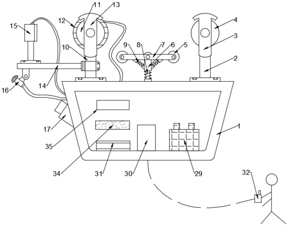
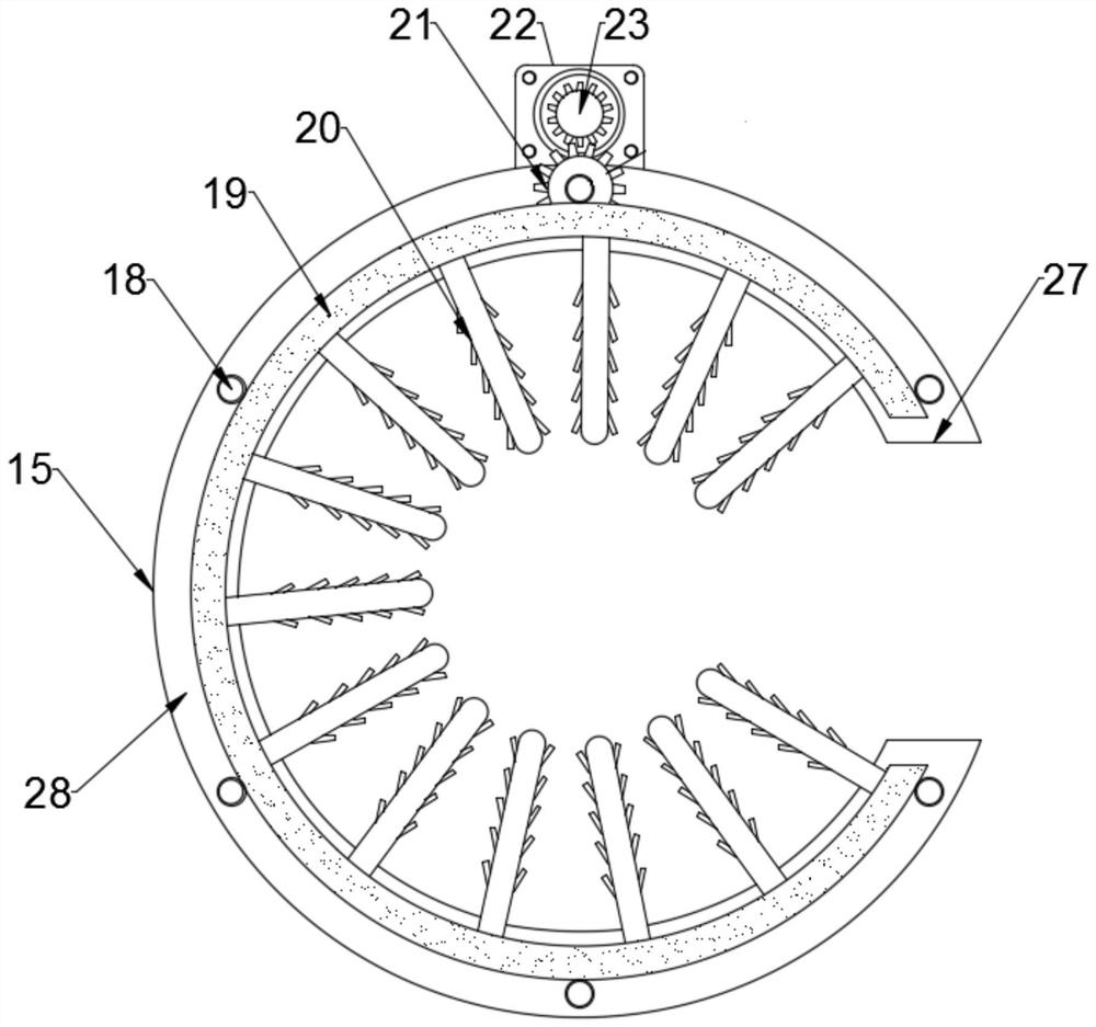
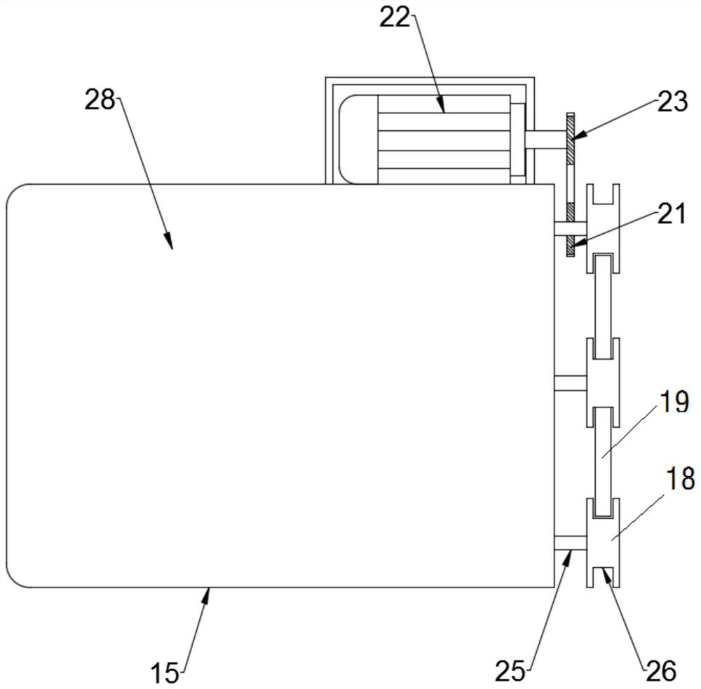
[0030] Specific embodiment one: as figure 1 , figure 2 , image 3 As shown, a power cable snow cleaning machine includes a housing 1, a first support frame 2, a first fixed frame 3, a first roller 4, a second roller 5, a support rod 6, a connecting rod 7, a first Spring 8 , second spring 9 , second supporting frame 10 , third roller 11 , motor 12 , second fixing frame 13 , fixing rod 14 and cleaning device 15 . A camera 17 is installed on one side of the outer wall of the housing 1 .
[0031] The first supporting frame 2 is arranged on the top of the casing 1 . The top of the first supporting frame 2 is welded with the first fixing frame 3 . The first roller 4 is installed on one side of the first fixed frame 3 .
[0032] The second supporting frame 10 is arranged on the top of the casing 1 . The top of the second supporting frame 10 is welded with the second fixing frame 13 . The third roller 11 is installed on one side of the second fixed frame 13 . The motor 12 is...
specific Embodiment 2
[0046] Specific embodiment two: as Figure 4 , Figure 5 As shown, a control system of a power cable snow sweeping machine, the specific structure of the power cable snow sweeping machine in the control system of the power cable snow sweeping machine refers to the first embodiment.
[0047] A control system for a power cable snow sweeper includes a first power supply 29 , a wireless receiver 30 , an IC controller 31 , a wireless transmitter 32 , a second power supply 33 , a data storage 34 and an image processing module 35 . The output terminal of the first power supply 29 is electrically connected with the input terminal of the wireless receiver 30 . The output end of the second power supply 33 is electrically connected to the input end of the wireless transmitter 32 . The output terminal of the wireless receiver 30 is electrically connected with the input terminal of the IC controller 31 . The output end of the image processing module 35 is electrically connected to the ...
PUM
 Abstract
Description
Claims
Application Information
 - Generate Ideas
- Intellectual Property
- Life Sciences
- Materials
- Tech Scout
- Unparalleled Data Quality
- Higher Quality Content
- 60% Fewer Hallucinations
Browse by: Latest US Patents, China's latest patents, Technical Efficacy Thesaurus, Application Domain, Technology Topic, Popular Technical Reports.
© 2025 PatSnap. All rights reserved.Legal|Privacy policy|Modern Slavery Act Transparency Statement|Sitemap|About US| Contact US: help@patsnap.com


