
A system and method for detecting leakage in a landfill area

A detection system and detection method technology, applied in landfill technology, application of electrical devices to test fluid tightness, etc., can solve problems such as differences in potential distribution, poor conductivity, and difficulty in meeting the needs of on-line monitoring of leakage in rigid landfills , to achieve the effect of improving monitoring efficiency and improving efficiency

Active Publication Date: 2022-07-05
CHINESE RES ACAD OF ENVIRONMENTAL SCI +1
View PDF6 Cites 0 Cited by
  • Summary
  • Abstract
  • Description
  • Claims
  • Application Information

AI Technical Summary

Problems solved by technology

However, the conductivity of the concrete medium of the rigid landfill structure is poor, and it is difficult to ensure the contact between the sensing electrode and the concrete, which greatly affects its applicability; the other is the online monitoring of leakage based on the principle of potential, and its basic principle is leakage The medium above and below the main anti-seepage barrier is connected, which leads to the difference in potential distribution
However, due to the rigid landfill structure, the space below the main anti-seepage barrier is relatively large (in order to allow people to enter, the lower space needs to be more than 60cm), and the amount of leachate leakage in the case of conventional leakage is difficult to make the leakage point above and below Media connectivity
Therefore, it is currently difficult to meet the online monitoring requirements for leakage in existing rigid landfills

Method used


Image

  • A system and method for detecting leakage in a landfill area
  • A system and method for detecting leakage in a landfill area
  • A system and method for detecting leakage in a landfill area

Examples


Embodiment 1

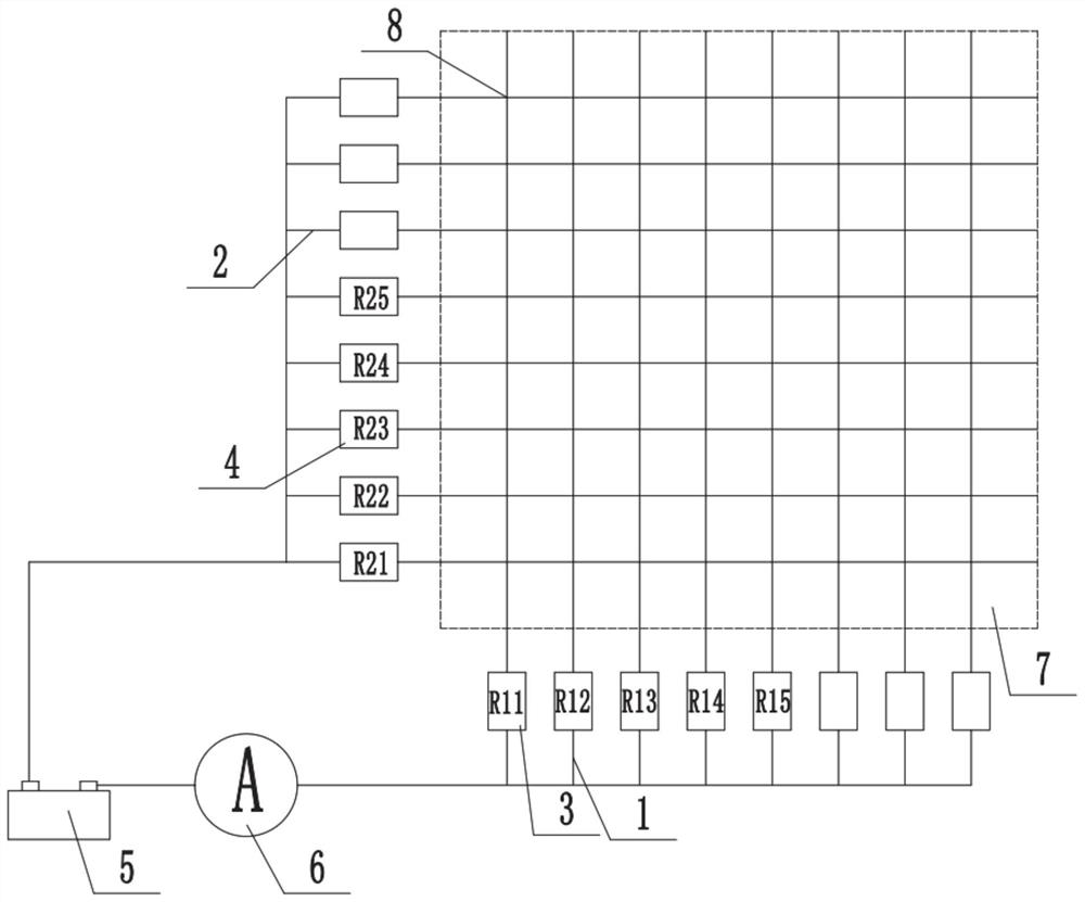
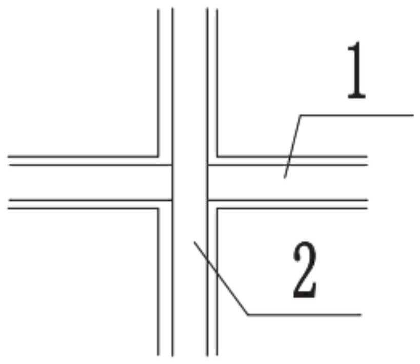
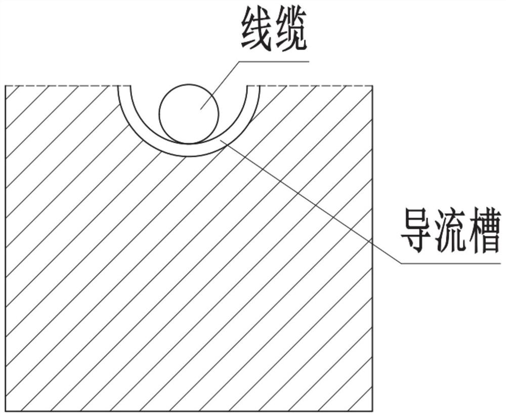
[0036] In a typical embodiment of the present disclosure, such as Figure 1-Figure 3 As shown, a landfill area leakage detection system is proposed.

[0037] like figure 1 As shown, in this embodiment, the detection system mainly includes a cable, a detection device 6 and a power supply 5, and the cable is arranged on the secondary impermeable layer 7 to obtain the leakage liquid in the landfill area above, and make the cable form a loop The detection device measures the resistance value of the loop formed by the cable, and obtains the corresponding position according to the resistance value, so as to achieve the purpose of detection and positioning; the power supply mainly supplies power to the cable and the detection device to form an electrified loop.

[0038] For the overall structural arrangement of the landfill area;

[0039] There is an anti-seepage structure around the landfill area. The inner wall of the anti-seepage structure forms a main anti-seepage barrier, that...

Embodiment 2

[0086] In another exemplary embodiment of the present disclosure, as Figure 1-Figure 3 As shown, a landfill area leakage detection method is provided, using the landfill area leakage detection system described in Embodiment 1.

[0087] The cables are arranged in a grid structure on the secondary anti-seepage layer below the main anti-seepage barrier, and connected to the power supply in series with resistors respectively;

[0088] The detection device monitors whether the cable forms a loop and the resistance of the loop in real time;

[0089] When no leakage occurs, the cables are all in an open circuit state, and the resistance value obtained by the detection device is infinite;

[0090] When leakage occurs, a first cable and a second cable conduct at the grid corresponding to the leakage to form a loop, and the resistance corresponding to the first cable forms a series connection with the resistance corresponding to the second cable. Obtain the total resistance value of ...


PUM


Abstract

The present disclosure provides a system and method for detecting leakage in a landfill area, and relates to the field of harmless landfill. One pole of the power supply, one end of all the second cables is respectively connected to the other pole of the power supply, the grid points are used to receive the leakage liquid and make the corresponding first cable and the second cable conduct to form a loop. The loops have different resistance values; the detection device is used to obtain the superimposed resistance value of the first cable and the second cable corresponding to the loop, so as to obtain the position of the grid point corresponding to the leakage, by setting the cable structure of the grid format , each grid point is connected to a different resistance value, corresponding to the landfill area above, when leakage occurs in the landfill area, the grid point is turned on, and the resistance value of the grid point is used to determine the position of the conductive grid point, thus Determine the location of the leak point corresponding to the landfill area, and locate the leak location.

Description

technical field [0001] The present disclosure relates to the field of harmless landfill, and in particular, to a system and method for detecting leakage in a landfill area. Background technique [0002] The statements in this section merely provide background related to the present disclosure and do not necessarily constitute prior art. [0003] Landfill is the main means of harmless disposal of hazardous waste, and for the harmless landfill of hazardous waste, the requirements for rigid landfill construction under the condition of high groundwater level, soft soil area and other geological conditions are proposed, which need to be The leakage and harmful components in the rigid landfill are monitored, and the damage and leakage of the landfill unit can be observed under artificial visual conditions, and repairs can be made in time. [0004] In order to achieve the purpose of timely observation and repair of leakage, it is necessary to arrange long-term manual duty and insp...

Claims


Application Information

Patent Timeline
Patent Type & Authority Patents(China)
IPC IPC(8): G01M3/40
CPCG01M3/40Y02W30/30
Inventor 徐亚姚光远郑开达刘景财能昌信刘玉强董路黄启飞薛祥山程亮
Owner CHINESE RES ACAD OF ENVIRONMENTAL SCI
Learn More