
Automatic particle plastic dehumidification drying system and technology

A drying system and plastic technology, applied in the direction of drying solid materials, dry cargo handling, drying gas arrangement, etc., can solve the problems of large drying load, easy softening, and sticking together of the drying device, so as to reduce the drying load and increase the contact area , the effect of increasing the contact time

Active Publication Date: 2020-08-07
山东华鹏高分子材料有限公司
View PDF12 Cites 6 Cited by
  • Summary
  • Abstract
  • Description
  • Claims
  • Application Information

AI Technical Summary

Problems solved by technology

[0003] In the existing dehumidification and drying system, the plastic particles are dried by hot air, and the plastic particles are stirred at the same time. This drying method has the following disadvantages: 1. The amount of plastic particles in the drying cylinder is large. Even if it is stirred, there are still many particles The lack of access to hot air leads to incomplete drying of the plastic granules, and the drying load of the drying device is also large; 2. In order to ensure that the plastic granules are completely dry, the plastic granules need to stay in the drying cylinder for a long time, and the first dried plastic granules last Heat easily softens and sticks together

Method used


Image

  • Automatic particle plastic dehumidification drying system and technology
  • Automatic particle plastic dehumidification drying system and technology
  • Automatic particle plastic dehumidification drying system and technology

Examples


Embodiment Construction

[0036] The embodiments of the present invention will be described in detail below with reference to the accompanying drawings, but the present invention can be implemented in many different ways defined and covered by the claims.

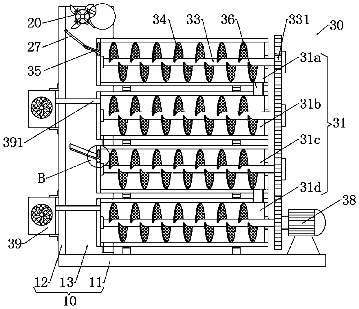
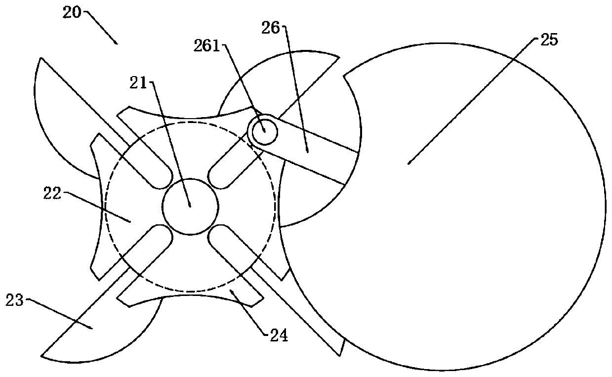
[0037] like figure 1 and figure 2 As shown, a granular plastic automatic dehumidification and drying system includes a base 10, a distribution device 20 installed on the base 10, and a drying device 30. The base 10 includes a bottom plate 11 and a side plate 12 vertically arranged at one end of the bottom plate 11. The bottom plate The top of 11 is located on the back side of side plate 12 and is vertically provided with back plate 13, and back plate 13 and side plate 12 are fixedly connected and perpendicular to each other, material distribution device 20 is located at the top of back plate 13, and drying device 30 is located at the top of bottom plate 11;

[0038]The material distribution device 20 includes a central shaft 21 vertically arranged...


PUM


Abstract

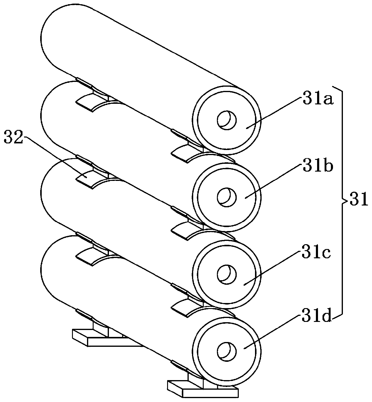
The invention relates to an automatic particle plastic dehumidification drying system and technology. The automatic particle plastic dehumidification drying system comprises a pedestal, a material distributing device and a drying device, wherein the material distributing device and the drying device are installed on the pedestal. The drying device comprises drying cylinders which are horizontallyarranged. Rotating shafts extending in the length directions of the drying cylinders are formed in the corresponding drying cylinders. Screw blades which are distributed in the length directions of the rotating shafts are arranged on the outer walls of the rotating shafts. According to the automatic particle plastic dehumidification drying system and technology, a grooved wheel is used for drivinga material receiving groove to rotate intermittently, and plastic particles are sequentially guided into the different drying cylinders through a material guide plate; and meanwhile, the plastic particles are subjected to primary dehumidification with feeding mechanisms at feeding inlets of the drying cylinders, and drying loads of the drying device are lowered. By means of the automatic particleplastic dehumidification drying system and technology, the screw blades are used for conveying the plastic particles, the plastic particles enter the next set of the drying cylinders through a firstcommunicating pipe, the time for the plastic particles to stay in the drying cylinders is prolonged, a hot-air blower is used for blowing reverse hot air into the drying cylinders, the contact area ofthe hot air and the plastic particles is increased, the contact time of the hot air and the plastic particles is prolonged and hence drying is made more thorough.

Description

technical field [0001] The invention relates to the technical field of granular plastics, in particular to an automatic dehumidification and drying system and a dehumidification and drying process for granular plastics. Background technique [0002] Plastic granules are granules processed from waste chemical plastics. The melted plastic is extruded and drawn into plastic strips. After being cooled by water, it is cut into plastic granules by a pelletizing device. The processed plastic granules have moisture on the surface, which does not meet the requirements of plastic products. Standard requirements, so it is necessary to dehumidify and dry the finished plastic granules. [0003] In the existing dehumidification and drying system, the plastic particles are dried by hot air, and the plastic particles are stirred at the same time. This drying method has the following disadvantages: 1. The amount of plastic particles in the drying cylinder is large. Even if it is stirred, the...

Claims


Application Information

Patent Timeline
Patent Type & Authority Applications(China)
IPC IPC(8): F26B17/20F26B21/00F26B5/16F26B25/00B29B13/06
CPCB29B13/065F26B5/16F26B17/205F26B21/001F26B25/002
Inventor 郭建设谷珍妮
Owner 山东华鹏高分子材料有限公司
Learn More