Assembly method and structure of pulley guide rail and its power catwalk
An assembly structure and assembly method technology, which is applied in the direction of earthwork drilling, drilling pipe, casing, etc., can solve the problems of difficult assembly process of block assembly and guide rail assembly, inability to perform assembly work, and difficult assembly process, etc., to achieve The assembly process is simple and easy, the action process is simple and easy, and the structure is reasonable
- Summary
- Abstract
- Description
- Claims
- Application Information
AI Technical Summary
Problems solved by technology
Method used
Image
Examples
Embodiment 1
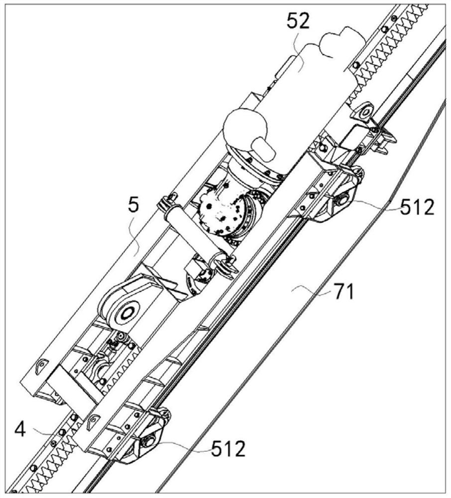
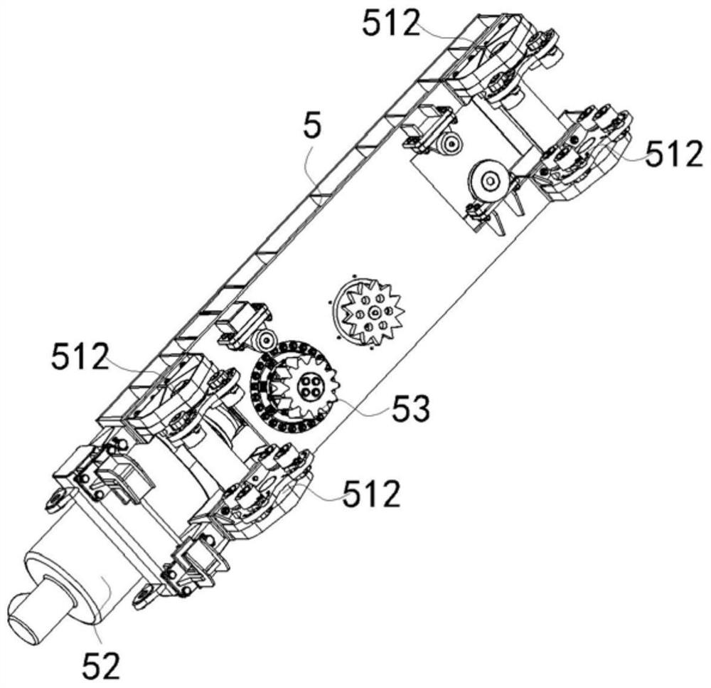
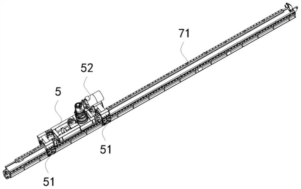
[0057] like Figure 3 to Figure 11 As shown, a method for assembling a pulley guide rail of the present embodiment includes the following steps:
[0058] S1: Place the pulley 5 on the top of the guide rail assembly, and the gear 53 assembled at the bottom of the pulley 5 meshes with the rack 4 on the top of the guide rail assembly;
[0059] S2: Sliding the roller disc unit 51 into the two sides of the guide rail assembly;
[0060] S3: On the guide rail assembly, the pulley 5 and the roller disc unit 51 are connected through the connecting piece 50 to form an integral structure.
[0061] When using the pulley guide rail assembly method of the present invention, it is obvious that the pulley assembly at least includes the pulley 5 and the roller disc unit 51, and the two are a split structure (a structure independent of each other); for the guide rail assembly, the Both sides can be matched with the roller disc unit 51, so that the roller disc unit 51 can be slidably inserted ...
Embodiment 2
[0071] like Figure 3 to Figure 11 As shown, a pulley guide rail assembly structure in this embodiment includes a pulley assembly and a guide rail assembly with a rack 4 at the top, the pulley assembly includes a pulley 5 and a roller disc unit 51, and the pulley 5 and the The roller disc unit 51 can be connected by the connecting piece 50 to form an integral structure; wherein,
[0072] The pulley 5 is placed on the top of the guide rail assembly, and the gear 53 assembled at the bottom of the pulley is engaged with the rack 4 on the top of the guide rail assembly;
[0073] The roller disc unit 51 is slidably inserted into both sides of the guide rail assembly;
[0074] The pulley 5 placed on the top of the guide rail assembly and the roller disc unit 51 embedded in the two sides of the guide rail assembly are connected by the connecting member 50 to form an integral structure.
[0075] When the pulley guide rail assembly structure of the present invention is adopted, thank...
Embodiment 3
[0081] In order to facilitate understanding of the present invention, the present invention specifically introduces a specific design of a guide rail assembly through the third embodiment.
[0082] like Figure 9 to Figure 11 As shown, a guide rail assembly in this embodiment includes guide rails 1 and 2; With the lower wing plate 1 12, the guide rail 2 includes a web plate 23, an upper wing plate 21 and a lower wing plate 2 22 arranged at the upper and lower ends of the web plate 2; along the length direction of the guide rail 1, 2 The upper wings 21 of each of the second guide rails 2 are respectively connected to both sides of the upper wings 11 of the guide rail 1 , and a rack 4 is provided on the top surface of the upper wings 11 . The guide rail 1 mainly plays the role of connecting two guide rails 2 , so that the guide rail assembly forms an integral structural form, and the guide rail 2 is used for direct load bearing.
[0083] preferably, as Figure 10 As shown, th...
PUM
 Abstract
Description
Claims
Application Information
 - R&D
- Intellectual Property
- Life Sciences
- Materials
- Tech Scout
- Unparalleled Data Quality
- Higher Quality Content
- 60% Fewer Hallucinations
Browse by: Latest US Patents, China's latest patents, Technical Efficacy Thesaurus, Application Domain, Technology Topic, Popular Technical Reports.
© 2025 PatSnap. All rights reserved.Legal|Privacy policy|Modern Slavery Act Transparency Statement|Sitemap|About US| Contact US: help@patsnap.com


