
Protection method with sealing structure and sealing protection tool

A sealing structure and tooling technology, applied in metal material coating process, liquid chemical plating, coating and other directions, can solve the problems of environmental pollution, uncontrollable quality of parts coating, high manufacturing cost, and achieve uniform coating quality and cost reduction. Significant synergy and good protective effect

Pending Publication Date: 2020-08-07
HARBIN DONGAN ENGINE GRP
View PDF5 Cites 0 Cited by
  • Summary
  • Abstract
  • Description
  • Claims
  • Application Information

AI Technical Summary

Problems solved by technology

This protection method has the following disadvantages: the protective sealing effect is unstable, the coating quality of the parts is uncontrollable, and the qualified rate is low; the protective material adheres to the surface of the parts, causing pollution to the parts and needs to be cleaned; the manual protection cycle is long and the production efficiency is low; the protective consumables Disposable use, high manufacturing cost; protective glue is toxic, pollutes the environment and damages health

Method used


Image

  • Protection method with sealing structure and sealing protection tool
  • Protection method with sealing structure and sealing protection tool
  • Protection method with sealing structure and sealing protection tool

Examples


Embodiment approach ( 1

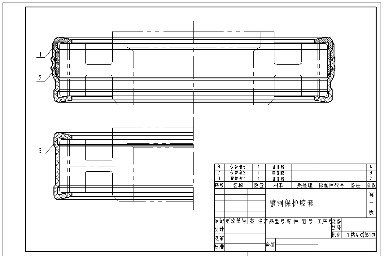
[0040] figure 1 Copper-plated protective tooling for a certain part: the structural design of the sealing protective tooling for the outer diameter end face of the straight tooth.

[0041] The sealing protective tooling is made of silicone rubber;

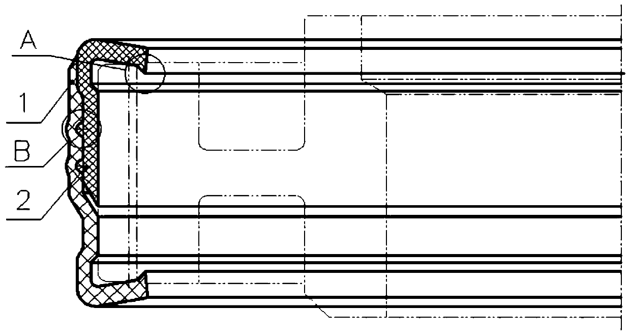
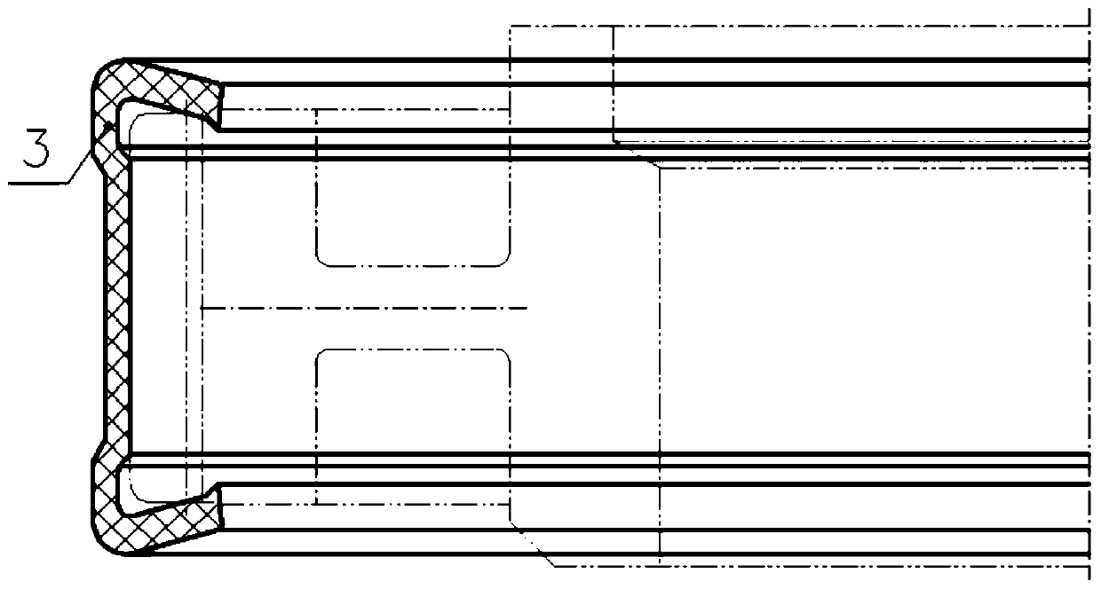
[0042] The sealing protective tooling is divided into split structure ( figure 2 ) and overall structure ( image 3 )design:

[0043] The sealing end of the sealing protective tooling is designed with a sealing lip structure A to increase the sealing effect of the protective sleeve;

[0044] There is sufficient tightness between the protective sleeve and the outer diameter of the protection;

[0045] There is a gap structure at the junction of the tooth top and the tooth side of the rubber protective sleeve, which reduces assembly resistance and increases the sealing effect of the end face.

[0046] For the split structure design, a locking buckle B (anti-skid lock) is designed between the inner and outer jackets.

[0047] A...

Embodiment approach ( 2

[0049] Electroless nickel-plated sealing protective tooling for external force ( Figure 4 ).

[0050] The protective structure includes a silicone rubber sleeve and a pressing plate pressing structure;

[0051] The rubber protective cover is a conformal protective structure ( Figure 5 );

[0052] Two-way compression between the parts through the spacer sleeve ( Image 6 );

[0053]According to the rubber protective structure of the end face of the straight tooth outer diameter, design the corresponding silicone rubber protective sleeve mold. Due to the complex structure of the parts, the selected silicone rubber has a Shore hardness of 40-45°, so that the processed silicone rubber protective sleeve has a good protective effect and is easy to install and disassemble.

[0054] The two ends of the silicone rubber protective sleeve apply external force through the pressure plate;

[0055] The protective part and the pressure applying device are fastened into one body throu...


PUM

PropertyMeasurementUnit
tensile strengthaaaaaaaaaa
Shore hardnessaaaaaaaaaa
elongationaaaaaaaaaa

Abstract

The invention belongs to the technical field of local protection of metal surface treatment, and relates to a protection method with a sealing structure and a sealing protection tool. The tool comprises protection covers and sealing lip structures, the protection covers seal protection parts, and the sealing lip structures seal the transition areas of the protection parts. The tool replaces an original tradition protection mode, the original mode for local protection through manual bonding and adhesive hanging is changed, the protection quality is improved, the efficiency is promoted, environmental protection and energy conservation are realized, and cost decreasing and benefit increasing are achieved.

Description

technical field [0001] The invention belongs to the technical field of partial protection for metal surface treatment, and relates to a protection method with a sealing structure and a sealing protection tool. Background technique [0002] Parts such as bearing housings, bushings, shafts, and discs of aeroengines need to be partially modified on the metal surface of specific areas of such parts by electroless plating, electroplating and other processes. Most of the surface modification process is carried out under high temperature, strong acid, strong alkali, and strong corrosion environment. Taking electroless nickel plating as an example, the temperature of the nickel plating bath is as high as 90°C, and the treatment time is long. The parts before nickel plating Strong acid and other strong corrosive chemical reagents are used for treatment, and strict protective measures must be taken on the non-plated surface of parts to ensure that there is no over-coating or corrosion...

Claims


Application Information

Patent Timeline
Patent Type & Authority Applications(China)
IPC IPC(8): C23C18/16C25D5/02
CPCC23C18/1605C25D5/022
Inventor 吴彦芬辛玉武吕文生师玉英孙振淋朱万宝关成武张胜宝刘星岑孙境尧
Owner HARBIN DONGAN ENGINE GRP
Learn More