Impurity cleaning device for material pneumatic transmission system

A pneumatic transmission and cleaning device technology, which is applied in the direction of transportation and packaging, conveying bulk materials, conveyors, etc., can solve the problems of complex electric warehouse opening structure, high maintenance cost, and pipeline wear, so as to eliminate the risk of high-altitude operations, and the overall The structure is simple and compact, and the effect of reducing equipment cost

Pending Publication Date: 2020-08-07
HUNAN SUNDY SCI & TECH DEV
View PDF0 Cites 1 Cited by
  • Summary
  • Abstract
  • Description
  • Claims
  • Application Information

AI Technical Summary

Problems solved by technology

[0005] (1) Affect the delivery efficiency
When there are foreign objects (residues) in the transmission pipeline or the packaging of the material to be transported is damaged and leaks into the transmission pipeline, these substances in the transmission pipeline will affect the normal operation of the material to be transported and seriously affect the delivery efficiency of the sample
[0006] (2) Difficult to clean and maintain
Since the pneumatic transmission pipeline is very long and very small (people cannot enter), it is very difficult to clean once foreign objects (residues) appear in the transmission pipeline
However, if it is not cleaned in time, it may cause the material to be transported to be stuck in the transmission pipeline. Once it is blocked, it will be more difficult to clean and dredge the pipeline, and the maintenance cost will be extremely high.
[0007] (3) Pipe wear is serious
There are the following disadvantages: First, if the method of manually opening the warehouse and discarding materials is adopted, due to the requirements of the location of the pipeline transmission layout, there is a risk of high-altitude operations, which is dangerous to a certain extent
Second, manual processing requires regular processing, which consumes high labor costs and takes a long time to clean up
Third, if the electric opening method is adopted, it is necessary to arrange the opening drive power cables along the entire pipeline, which requires a large amount of engineering, and at the same time, the structure of the electric opening is complicated and the equipment cost is high

Method used


Image

  • Impurity cleaning device for material pneumatic transmission system
  • Impurity cleaning device for material pneumatic transmission system
  • Impurity cleaning device for material pneumatic transmission system

Examples


Embodiment Construction

[0030] The present invention will be described in further detail below in conjunction with specific embodiments and accompanying drawings.

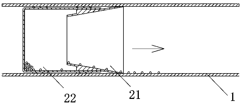
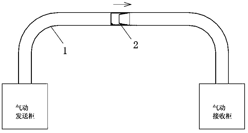
[0031] Such as Figure 1 to Figure 4 As shown, the present invention provides an impurity cleaning device for a material pneumatic conveying system, which includes a moving body 2 that can be pneumatically conveyed in a pneumatic conveying pipeline 1, and the length of the moving body 2 is not longer than 2 meters. At least one end opening of the mobile body 2 forms a shovel portion 21 for shoveling impurities in the pneumatic transmission pipeline 1 into the mobile body 2 for collection during transmission of the mobile body 2 . The specific implementation principle is as follows:

[0032] When the operator thinks it needs to be cleaned, he can put the impurity cleaning device directly into the pneumatic transmission pipeline 1 at any time, and then operate the pneumatic transmission system normally, so that the mobile body 2 is pneumat...


PUM


Abstract

The invention discloses an impurity cleaning device for a material pneumatic transmission system. A moving body capable of conducting pneumatic transmission in a pneumatic transmission pipeline is included. At least one end of the moving body is opened to form a shovel barrel part so that during transmission of the moving body, the shovel barrel part can be used for shoveling impurities in the pneumatic transmission pipeline into the moving body for collection. The impurity cleaning device has the advantages that the structure is simple and compact, the manufacturing cost is low, operation iseasy, foreign matter in the pneumatic transmission pipeline can be collected in time, the interior of the pneumatic transmission pipeline is kept clean, and maintaining is easy.

Description

technical field [0001] The invention mainly relates to the field of equipment for collecting and processing material samples, and in particular to an impurity cleaning device used in a material pneumatic transmission system. Background technique [0002] For the sampling, sample preparation, and testing of material (such as ore, coal) samples, each country has mandatory standards, and the sampling and processing of samples must be carried out in accordance with the standards. The principle of sample sampling, sample preparation, and testing work process is to gradually reduce the particle size and quality of the collected samples without destroying the representativeness of the sample, until it meets the particle size and quality of the sample in the laboratory test ( Weight) accuracy requirements, and then carry out relevant laboratory analysis on the samples that meet the requirements. [0003] For example, taking coal sampling as an example, it is actually a sampling and...

Claims


Application Information

Patent Timeline
Patent Type & Authority Applications(China)
IPC IPC(8): B65G53/52B65G53/34
CPCB65G53/34B65G53/521
Inventor 何习达
Owner HUNAN SUNDY SCI & TECH DEV
Why Eureka
Try Eureka