
Limiting structure of mechanical arm and mechanical arm

A technology of mechanical arm and limit structure, which is applied to workbenches, workpiece clamping devices, manufacturing tools, etc., can solve the problems of not being able to determine the specific parameters of the limit as soon as possible, reduce the machining accuracy, and prolong the production cycle, so as to shorten the production. Cycle time, improved machining accuracy, and improved interchangeability

Active Publication Date: 2020-08-07
CHANGZHOU INST OF MECHATRONIC TECH +1
View PDF8 Cites 2 Cited by
  • Summary
  • Abstract
  • Description
  • Claims
  • Application Information

AI Technical Summary

Problems solved by technology

[0003] 1. Compared with the processing parts of the same batch, the clamping parameters need to be readjusted each time during manual operation, so the cumulative error generated is high and the processing accuracy is reduced;
[0004] 2. Compared with large parts that need to be processed by indexing, it is often necessary to lift and flip when processing different positions, and reposition after flipping. The entire operation process takes a long time and reduces the positioning accuracy;
[0005] 3. Compared with different parts, the limit process needs to repeat multiple adjustment steps, and the specific parameters of the limit cannot be determined as soon as possible, which prolongs the production cycle of processing

Method used


Image

  • Limiting structure of mechanical arm and mechanical arm
  • Limiting structure of mechanical arm and mechanical arm
  • Limiting structure of mechanical arm and mechanical arm

Examples


Embodiment Construction

[0031] The technical solutions in the embodiments of the present invention will be clearly and completely described below in conjunction with the accompanying drawings in the embodiments of the present invention. Obviously, the described embodiments are only a part of the embodiments of the present invention, rather than all the embodiments. Based on the embodiments of the present invention, all other embodiments obtained by those of ordinary skill in the art without creative work shall fall within the protection scope of the present invention.

[0032] See Figure 1-7 , The present invention provides a technical solution:

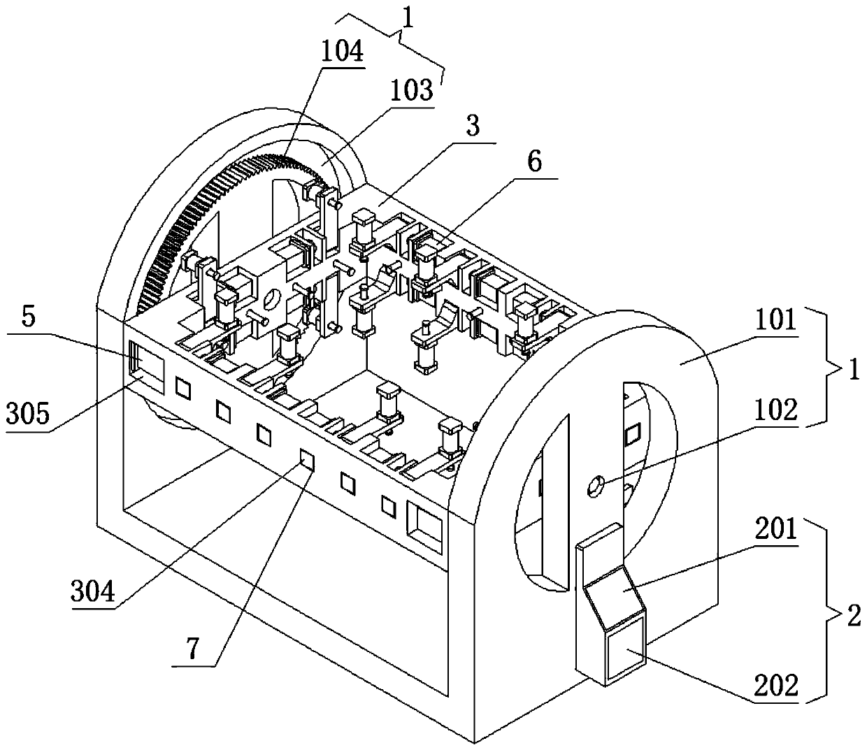
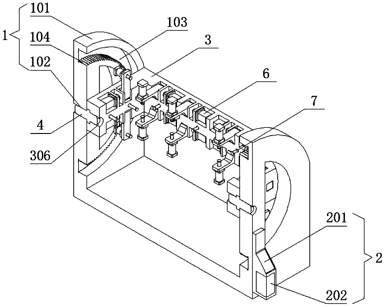
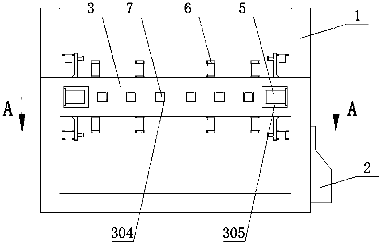
[0033] A limit structure of a mechanical arm and a mechanical arm, including a support frame assembly, a flip frame assembly arranged in the middle of the support frame assembly, and a limit assembly set on the flip frame assembly. The support frame assembly consists of a support frame 1 and a support frame 1. The control center 2 is set on the side. The turni...


PUM


Abstract

The invention discloses a limiting structure of a mechanical arm and the mechanical arm. The limiting structure comprises a support frame component, a roll-over stand component arranged at the middleof the support frame component and a limiting component arranged on the roll-over stand component; the support frame component is composed of a support frame and a control center arranged at the sidesurface of the support frame; the roll-over stand component is composed of a roll-over stand, a rotating shaft and a driving component; and the limiting component is composed of limiting components atthe upper and lower ends and a side limiting electric cylinder. Relative to processed parts of the same batch, limit parameters are only needed to be set for one time, so that the generated accumulative error is small, the machining precision is improved, and the interchangeability of the same batch of parts is improved; and compared with large parts that need to be rotated and processed, a driving motor is driven to enable a drive gear to be in engaged transmission with a gear, a workpiece on the roll-over stand can be turned over around a middle rotating shaft hole I, and the positioning precision is improved.

Description

Technical field [0001] The invention relates to the technical field of machining positioning, in particular to a limit structure of a mechanical arm and a mechanical arm. Background technique [0002] In order to ensure the machining accuracy of parts in mechanical processing, corresponding tooling is usually used for limiting and fixing operations during mass production or in order to improve accuracy. The limiting tooling in the prior art is generally simple and has less structure. The processing is simple, the cost is low, and it can meet the general requirements of mechanical processing. However, in actual use, the existing mechanical limit tooling still has the following shortcomings: [0003] 1. Compared with the processed parts of the same batch, manual operation requires re-adjusting the clamping parameters every time, so the accumulated error is higher and the processing accuracy is reduced; [0004] 2. Compared with large parts that need to be indexed, it is often necessar...

Claims


Application Information

Patent Timeline
Patent Type & Authority Applications(China)
IPC IPC(8): B25B11/00B25H1/10
CPCB25B11/00B25H1/10
Inventor 虞文武沈琳张波周辉锋
Owner CHANGZHOU INST OF MECHATRONIC TECH
Learn More