
Prediction method of crack propagation life of aircraft body

A technology of crack extension life and aircraft body, applied in the direction of applying repeated force/pulsation force to test the strength of materials, etc., can solve the problems of complex calculation process, long time consumption, and increased cumulative error

Active Publication Date: 2015-07-22
BEIJING AERONAUTIC SCI & TECH RES INST OF COMAC +1
View PDF5 Cites 28 Cited by
  • Summary
  • Abstract
  • Description
  • Claims
  • Application Information

AI Technical Summary

Problems solved by technology

When the above-mentioned analysis method is applied to the calculation and prediction of the crack growth life of aircraft structure, there are the following problems: (1) the crack structure on the aircraft and the aircraft is complex;
[0009] (2) Due to the complex and changeable environment in which the aircraft is located, the load spectrum imposed on the aircraft during flight is highly complex, highly random, and has a large number of cycles;
[0010] (3) When analyzing the cracks on the aircraft structure, it is necessary to update the model and re-mesh frequently based on the expansion of the cracks. It is determined that the cumulative error in the calculation process increases significantly with the increase of calculation time, and the resulting final calculation accuracy is poor;
[0011] (4) When the finite element method is used for stress analysis in the calculation process, if the accuracy of the calculation is to be ensured, the difference in unit size should not be too large when the model is divided into meshes. The unit needs to be fully refined, so the total number of units in the model increases greatly, resulting in an excessive amount of calculation

Method used


Image

  • Prediction method of crack propagation life of aircraft body
  • Prediction method of crack propagation life of aircraft body
  • Prediction method of crack propagation life of aircraft body

Examples


Embodiment Construction

[0054] The technical solutions of the present invention will be further described below in conjunction with the accompanying drawings and through specific implementation methods.

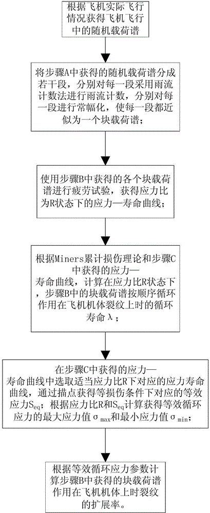
[0055] Such as figure 1 Shown is the aircraft body crack growth life prediction method in the present invention, comprising the following steps: Step A: Obtain the random load spectrum in the aircraft flight according to the actual flight conditions of the aircraft;

[0056] Step B: Divide the random load spectrum obtained in step A into several sections, use the rainflow counting method to count rainflow for each section, and perform constant amplitude for each section, so that each section is approximated as a block load spectrum;

[0057] Step C: use the load spectrum of each block obtained in step B to perform a fatigue test, and obtain the stress-life curve under the state where the stress ratio is R;

[0058] Step D: According to Miners cumulative damage theory and the stress-life curve obtai...


PUM


Abstract

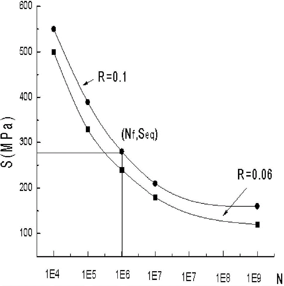
The invention discloses a prediction method of a crack propagation life of an aircraft body. The prediction method comprises the following steps: obtaining a random loading spectrum of an aircraft in flight according to the practical flight situation of the aircraft; dividing the obtained random loading spectrum into a plurality of sections, and respectively performing rain-flow counting and constant amplitude on each section, so that each section is approximated as a block loading spectrum; according to an Miners progressive damage theory, calculating a cycle life lambda effected on a crack of each block loading spectrum under the state of a corresponding stress ratio R, performing a fatigue test under the suitable stress ratio, and obtaining a corresponding stress-life curve; according to an equal defect theory, selecting the correspondence life curve under the suitable stress ratio R in the stress-life curve, and obtaining the equivalent stress Seq corresponding to the same life by a point tracing method; then, according to the R and the Seq, obtaining a maximum stress value sigma max and a minimum stress value sigma min of the equivalent cyclic stress; according to parameters of the equivalent cyclic stress, calculating the propagation rate of the crack when the obtained block loading spectrum is acted on the aircraft body.

Description

technical field [0001] The invention relates to the fields of fracture mechanics and damage tolerance, and more specifically discloses a method for predicting the crack growth life of an aircraft body under a random load spectrum. Background technique [0002] The life prediction process of mechanical structure crack growth under random load spectrum is very complicated and the prediction efficiency is low. In the prior art, the following steps are generally followed when analyzing the crack growth life of a mechanical structure: [0003] (1) Construct the same geometric model as the actual structure in the analysis software, and the geometric model contains the initial defects to be analyzed; [0004] (2) In the analysis software, according to the load spectrum applied to the mechanical structure in actual use, load is applied to the geometric model and stress analysis is performed; [0005] (3) Obtained the stress at the distal end of the crack under the load of the init...

Claims


Application Information

Patent Timeline
IPC IPC(8): G01N3/32
Inventor 张金玲张嘉振
Owner BEIJING AERONAUTIC SCI & TECH RES INST OF COMAC
Learn More